


REAR SUSPENSION AND DRIVE LINE 4-8
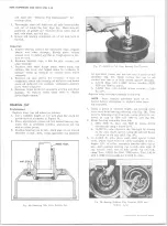
The seal is mounted on the pinion flange which is splined
and bolted to the hypoid pinion shaft.
The hypoid ring gear is bolted to a one-piece differen
tial case which is supported by a two preloaded tapered
roller bearings.
SERIES 20 5500 LB. CAPACITY AXLES (D A N A )
The 5500 lb. capacity axle is a Salisbury Design full
floating axle. Their service procedures are a combina
tion of Series 10 Salisbury axle procedures and Series
20-30, 5200, 5500 lb. capacity axle service procedures.
Consequently, refer to Series 10, 3300 and 3500 lb.
capacity axle service procedures for service on the dif
ferential such as pinion shaft oil seal and companion
flange and to Series 20-30, 5200 - 7200 lb. capacity axles
service procedures for service on wheel hubs, bearings,
and axle shafts.
SERIES 20-30 5200 A N D 7200 LB.
CAPACITY AXLES
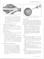
The 5200 and 7200 lb. capacity truck rear axles (fig„ 16)
are of the full floating type with hypoid ring gear and
drive pinion. The full floating construction enables easy
removal of axle shafts without removing truck load and
without jacking up the axle. The differential carrier is
heavily ribbed to provide rigid support for the differential
assembly--differential caps are doweled to the carrier to
assure perfect alignment.
The straddle-mounted drive pinion is supported at the
front by two opposed tapered roller bearings. The pinion
rear bearing is a roller bearing assembly consisting of
an outer race and roller assembly--a precision ground
diameter on the pinion pilot functions as an inner race.
A thrust pad mounted on the end of an adjustable screw
threaded into the carrier housing limits deflection of the
ring gear under high torque conditions.
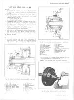
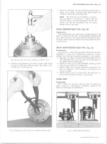
1. Nut
2. Washer
3. Companion Flange
4.
Deflector
5. Seal
6. Slinger
Fig. 15A— Dana 5500 lb. Capacity A x le — Cross Section
7. Shim
8. Drive Pinion
9. Shim
10. Shim
11. Differential Side Bearing
12. Gasket
13. Pinion Shaft Lock Screw
14. Differential Side G ear
15. Thrust Washer
16. Differential Pinion G ear
17. Thrust Washer
18. Differential Case
19. Differential Pinion
20. Ring G ear
21. Axle Shaft
22. Drive Pinion Rear Bearing
23. Drive Pinion Front Bearing
10-30 CHEVROLET TRUCK SERVICE MANUAL
Содержание 10 1971 Series
Страница 1: ......
Страница 96: ......
Страница 100: ...10 30 CHEVROLET TRUCK SERVICE MANUAL Fig 4 10 30 Series Truck Frame FRAME 2 4 ...
Страница 120: ......
Страница 203: ...ENGINE 6 25 Fig 22L Engine Mounts 10 30 CHEVROLET TRUCK SERVICE MANUAL ...
Страница 215: ...ENGINE 6 37 REAR M O U NT Fig 21V Engine Mounts 10 30 CHEVROLET TRUCK SERVICE MANUAL ...
Страница 218: ......
Страница 249: ......
Страница 250: ...EMISSION CONTROL SYSTEMS 6T 4 Fig 3 Combination Emission Control System Routing V8 10 30 CHEVROLET TRUCK SERVICE MANUAL ...
Страница 324: ......
Страница 339: ...FUEL TANK AND EXHAUST SYSTEMS 8 15 SPECIAL TOOLS Fig 22 Special Tools 1 J 23346 Fuel Tank Gauge Remover and Installer ...
Страница 340: ......
Страница 365: ...10 30 CHEVROLET TRUCK SERVICE MANUAL Fig 43 Power Steering Pump M ounting STEERING 9 25 ...
Страница 368: ......
Страница 386: ......
Страница 390: ...ELECTRICAL BODY AND CHASSIS 12 4 10 30 CHEVROLET TRUCK SERVICE MANUAL ...
Страница 391: ......
Страница 392: ...ELECTRICAL BODY AND CHASSIS 12 6 Fig 5 Rear Lighting Composite 10 30 CHEVROLET TRUCK SERVICE MANUAL ...
Страница 409: ...ELECTRICAL BODY AND CHASSIS 12 23 Fig 27 Engine Compartment CA30 02 10 30 CHEVROLET TRUCK SERVICE MANUAL ...
Страница 410: ...ELECTRICAL BODY AND CHASSIS 12 24 18DK GRN 19 Fig 28 Instrument Panel CA30 02 10 30 CHEVROLET TRUCK SERVICE MANUAL ...
Страница 411: ...ELECTRICAL BODY AND CHASSIS 12 25 Fig 29 Instrument Panel CA30 02 10 30 CHEVROLET TRUCK SERVICE MANUAL ...
Страница 412: ...ELECTRICAL BODY AND CHASSIS 12 26 fh Ar r kk 4 Fig 30 Engine Compartment C A K A 10 20 CA30 03 z _ ...
Страница 416: ...ELECTRICAL BODY AND CHASSIS 12 30 Fig 34 Engine Compartment CA KA10 20 CA30 04 10 30 CHEVROLET TRUCK SERVICE MANUAL ...
Страница 420: ...ELECTRICAL BODY AND CHASSIS 12 34 Fig 38 Engine Compartment C A K A 1 0 20 06 16 10 30 CHEVROLET TRUCK SERVICE MANUAL ...
Страница 422: ...ELECTRICAL BODY AND CHASSIS 12 36 Fig 40 Instrument Panel C A K A 10 20 06 16 10 30 CHEVROLET TRUCK SERVICE MANUAL ...
Страница 423: ...ELECTRICAL BODY AND CHASSIS 12 37 Fig 41 R ear Lamps C A K A 1 0 20 06 16 10 30 CHEVROLET TRUCK SERVICE MANUAL ...
Страница 424: ...ELECTRICAL BODY AND CHASSIS 12 38 Fig 42 Engine Compartment CA KA10 20 CAl30 14 34 10 30 CHEVROLET TRUCK SERVICE MANUAL ...
Страница 426: ...ELECTRICAL BODY AND CHASSIS 12 40 Fig 44 Instrument Panel CA KA10 20 CA30 14 34 10 30 CHEVROLET TRUCK SERVICE MANUAL ...
Страница 428: ......
Страница 432: ......
Страница 449: ...SPECIFICATIONS 9 10 30 CHEVROLET TRUCK SERVICE MANUAL ...
Страница 463: ......
Страница 464: ......
Страница 465: ......
Страница 466: ......


