


HEATER AND AIR CONDITIONING 1A-19
• Check the switch adjusting screw for stripped or
otherwise damaged threads,,
Adjusting Switch
If, after the above checks, the switch seems to be op
erating properly, adjust for proper setting if necessary,
as follows:
1. Vehicle must be set up as described in "Perform
ance Test."
2. The suction side of the system, read on the low
pressure gauge, should pull down to the pressure
shown in the chart in "Performance Data" under the
ambient temperature at the time the switch is being
set.
3. Roof-Mounted System - Remove the rear duct screws
and then remove the duct from its side retaining
flanges.
It is not necessary to remove the duct
from its rear retaining flange or disconnect the rear
drain tubes.
GM Chevrolet System - Lower the entire unit from
its dash mounting, remove the duct assembly from
the blower-evaporator unit and then remove the duct
rear cover.
4. Disconnect the switch wiring harness, remove the
switch attaching screws and remove the switch.
NOTE:
On GM Chevrolet Units, the knob must
be pulled off the switch shaft before the switch
can be removed.
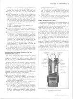
5. Remove the switch non-metal end plate to gain ac
cess to the switch adjusting screw.
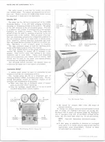
6. If the outlet temperature was less than the pre
scribed temperature at the end of each cooling cycle,
turn the adjusting screw a partial turn counter
clockwise (fig. 28). If the outlet temperature was
more than prescribed temperature, turn the adjusting
screw clockwise.
NOTE:
One turn of the adjusting screw will
change the outlet temperature approximately 4
degrees.
7. Reinstall switch end plate and install switch. Rein
stall ducts removed in Step 3 above. Be sure that
the air sensing capillary has been replaced properly,
if removed during disassembly.
8. Check system performance. If further adjustment
is needed, repeat Steps 3 through 7 until the pre
scribed pressure is reached.
CAUTION:
Do not attempt to run a Perform
ance Check with the system disassembled since
inaccurate readings would be the result. AL
WAYS reinstall the duct work before running a
performance check.
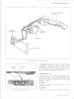
EXPAN SIO N VALVE (Fig. 29)
A malfunction of the -expansion valve will be caused by
one of the following conditions; valve stuck open, valve
stuck closed, broken power element, a restricted screen
or an improperly located or installed power element bulb.
The first three conditions require valve replacement.
The last two may be corrected by replacing the valve inlet
screen and by properly installing the power element bulb.
Attachment of the expansion valve bulb to the evaporator
outlet pipe is very critical. The bulb must be attached
tightly to the pipe and must make good contact with the
pipe along the entire length of the bulb. A loose bulb will
result in high POA pressures and poor cooling. On
bulbs located outside the evaporator case, insulation must
be properly installed.
Indications of expansion valve trouble provided by the
Performance Test are as follows:
VALVE STUCK OPEN
Noisy Compressor.
No Cooling - Freeze Up.
VALVE STUCK CLOSED, P L U G G E D SCREEN OR
BROKEN POWER ELEMENT
Very Low Suction Pressure.
No Cooling.
EXTERNAL
EQUALIZER
LINE
OUTLET
Fig. 2 8 — Thermostatic Switch Adjustment
Fig. 2 9 — Expansion Valve
10-30 CHEVROLET TRUCK SERVICE MANUAL
Содержание 10 1971 Series
Страница 1: ......
Страница 96: ......
Страница 100: ...10 30 CHEVROLET TRUCK SERVICE MANUAL Fig 4 10 30 Series Truck Frame FRAME 2 4 ...
Страница 120: ......
Страница 203: ...ENGINE 6 25 Fig 22L Engine Mounts 10 30 CHEVROLET TRUCK SERVICE MANUAL ...
Страница 215: ...ENGINE 6 37 REAR M O U NT Fig 21V Engine Mounts 10 30 CHEVROLET TRUCK SERVICE MANUAL ...
Страница 218: ......
Страница 249: ......
Страница 250: ...EMISSION CONTROL SYSTEMS 6T 4 Fig 3 Combination Emission Control System Routing V8 10 30 CHEVROLET TRUCK SERVICE MANUAL ...
Страница 324: ......
Страница 339: ...FUEL TANK AND EXHAUST SYSTEMS 8 15 SPECIAL TOOLS Fig 22 Special Tools 1 J 23346 Fuel Tank Gauge Remover and Installer ...
Страница 340: ......
Страница 365: ...10 30 CHEVROLET TRUCK SERVICE MANUAL Fig 43 Power Steering Pump M ounting STEERING 9 25 ...
Страница 368: ......
Страница 386: ......
Страница 390: ...ELECTRICAL BODY AND CHASSIS 12 4 10 30 CHEVROLET TRUCK SERVICE MANUAL ...
Страница 391: ......
Страница 392: ...ELECTRICAL BODY AND CHASSIS 12 6 Fig 5 Rear Lighting Composite 10 30 CHEVROLET TRUCK SERVICE MANUAL ...
Страница 409: ...ELECTRICAL BODY AND CHASSIS 12 23 Fig 27 Engine Compartment CA30 02 10 30 CHEVROLET TRUCK SERVICE MANUAL ...
Страница 410: ...ELECTRICAL BODY AND CHASSIS 12 24 18DK GRN 19 Fig 28 Instrument Panel CA30 02 10 30 CHEVROLET TRUCK SERVICE MANUAL ...
Страница 411: ...ELECTRICAL BODY AND CHASSIS 12 25 Fig 29 Instrument Panel CA30 02 10 30 CHEVROLET TRUCK SERVICE MANUAL ...
Страница 412: ...ELECTRICAL BODY AND CHASSIS 12 26 fh Ar r kk 4 Fig 30 Engine Compartment C A K A 10 20 CA30 03 z _ ...
Страница 416: ...ELECTRICAL BODY AND CHASSIS 12 30 Fig 34 Engine Compartment CA KA10 20 CA30 04 10 30 CHEVROLET TRUCK SERVICE MANUAL ...
Страница 420: ...ELECTRICAL BODY AND CHASSIS 12 34 Fig 38 Engine Compartment C A K A 1 0 20 06 16 10 30 CHEVROLET TRUCK SERVICE MANUAL ...
Страница 422: ...ELECTRICAL BODY AND CHASSIS 12 36 Fig 40 Instrument Panel C A K A 10 20 06 16 10 30 CHEVROLET TRUCK SERVICE MANUAL ...
Страница 423: ...ELECTRICAL BODY AND CHASSIS 12 37 Fig 41 R ear Lamps C A K A 1 0 20 06 16 10 30 CHEVROLET TRUCK SERVICE MANUAL ...
Страница 424: ...ELECTRICAL BODY AND CHASSIS 12 38 Fig 42 Engine Compartment CA KA10 20 CAl30 14 34 10 30 CHEVROLET TRUCK SERVICE MANUAL ...
Страница 426: ...ELECTRICAL BODY AND CHASSIS 12 40 Fig 44 Instrument Panel CA KA10 20 CA30 14 34 10 30 CHEVROLET TRUCK SERVICE MANUAL ...
Страница 428: ......
Страница 432: ......
Страница 449: ...SPECIFICATIONS 9 10 30 CHEVROLET TRUCK SERVICE MANUAL ...
Страница 463: ......
Страница 464: ......
Страница 465: ......
Страница 466: ......