CHASSIS SHEET METAL 11-6
Fig. 10— Running Board— CA310-360 (04) Models
7. Disconnect fan shroud and lay back on engine.
8. Remove both head lamp assemblies. Complete.
9. Remove left fender gusset (5 screws).
10. Remove screws securing fender skirts to radiator
support bottom.
11. Remove bolt securing center grille support to radia
tor support.
12. Remove bolts securing hood catch assembly to radia
tor support.
13. Remove radiator support bolts secured to frame--
Note and record stackup.
14. Tilt radiator support rearward and lift up and off.
Installation
1. Rotate radiator support into position and loosely in
stall attachments to frame.
2. Connect center grille support to radiator support.
3. Connect hood latch plate.
4. Connect left radiator support gusset to left fender.
5. Connect support to left fender.
6. Connect 3 screws from underside of left skirt to
support bottom.
7. Place right fender in position and loosely install
bolts and shims at fender top to cowl.
8. Attach grille upper to right fender bolts loosely.
9. Attach bolts from inside of grille lower to right
fender lower (limited access between radiator sup
port outer face and grille inner face).
10. Install radiator support to fender.
11. Using drift line up right fender skirt rearmost bot
tom screw with fender flange and attach loosely.
12. Attach right fender skirt inner top bolts to fender
underside.
13. Install screw from underside of skirt to center of
fender flange.
14. Tighten rearmost bottom screw offender skirt pre
viously installed loosely.
15. Install remainder of skirt to right fender screws
snugly.
16. Tighten right fender skirt front 3 bolts from under
side to radiator support.
17. Place battery tray in position and fasten to radiator
support.
18. From beneath skirt fasten screw to battery tray
bottom.
19. Install bolt and shim at bottom of front fender rear
to hinge pillar loosely.
20. Tighten 6 grille filler panel screws previously at
tached to radiator support.
21. Install radiator, hoses and shroud.
22. Connect removed wiring to radiator support.
23. Install both head lamp assemblies.
24. Tighten all previously installed bolts and screws,
attached.
27. Install hood on previously marked outline.
28. Install and secure cowl grille.
25. Install battery and connect leads and wires.
26. Fill radiator with coolant as specified in Section 13.
FRONT FENDER
Removal
1. Remove windshield wiper arms, cowl grille and at
taching screws.
2. Remove hood and hinge assembly.
3. Remove head lamp bezel, wiring and attachments
from fender.
4. Remove screws attaching fender wheel opening flange
to skirt.
5. Remove (2) skirt to fender bolts, located inboard on
underside of skirt.
6. Remove two screws attaching gusset to fender.
FRAME
FRAME SIDEMEMBER
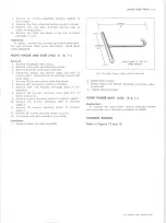
Fig. 11— Running Board and Braces
10-30 CHEVROLET TRUCK SERVICE MANUAL
Содержание 10 1971 Series
Страница 1: ......
Страница 96: ......
Страница 100: ...10 30 CHEVROLET TRUCK SERVICE MANUAL Fig 4 10 30 Series Truck Frame FRAME 2 4 ...
Страница 120: ......
Страница 203: ...ENGINE 6 25 Fig 22L Engine Mounts 10 30 CHEVROLET TRUCK SERVICE MANUAL ...
Страница 215: ...ENGINE 6 37 REAR M O U NT Fig 21V Engine Mounts 10 30 CHEVROLET TRUCK SERVICE MANUAL ...
Страница 218: ......
Страница 249: ......
Страница 250: ...EMISSION CONTROL SYSTEMS 6T 4 Fig 3 Combination Emission Control System Routing V8 10 30 CHEVROLET TRUCK SERVICE MANUAL ...
Страница 324: ......
Страница 339: ...FUEL TANK AND EXHAUST SYSTEMS 8 15 SPECIAL TOOLS Fig 22 Special Tools 1 J 23346 Fuel Tank Gauge Remover and Installer ...
Страница 340: ......
Страница 365: ...10 30 CHEVROLET TRUCK SERVICE MANUAL Fig 43 Power Steering Pump M ounting STEERING 9 25 ...
Страница 368: ......
Страница 386: ......
Страница 390: ...ELECTRICAL BODY AND CHASSIS 12 4 10 30 CHEVROLET TRUCK SERVICE MANUAL ...
Страница 391: ......
Страница 392: ...ELECTRICAL BODY AND CHASSIS 12 6 Fig 5 Rear Lighting Composite 10 30 CHEVROLET TRUCK SERVICE MANUAL ...
Страница 409: ...ELECTRICAL BODY AND CHASSIS 12 23 Fig 27 Engine Compartment CA30 02 10 30 CHEVROLET TRUCK SERVICE MANUAL ...
Страница 410: ...ELECTRICAL BODY AND CHASSIS 12 24 18DK GRN 19 Fig 28 Instrument Panel CA30 02 10 30 CHEVROLET TRUCK SERVICE MANUAL ...
Страница 411: ...ELECTRICAL BODY AND CHASSIS 12 25 Fig 29 Instrument Panel CA30 02 10 30 CHEVROLET TRUCK SERVICE MANUAL ...
Страница 412: ...ELECTRICAL BODY AND CHASSIS 12 26 fh Ar r kk 4 Fig 30 Engine Compartment C A K A 10 20 CA30 03 z _ ...
Страница 416: ...ELECTRICAL BODY AND CHASSIS 12 30 Fig 34 Engine Compartment CA KA10 20 CA30 04 10 30 CHEVROLET TRUCK SERVICE MANUAL ...
Страница 420: ...ELECTRICAL BODY AND CHASSIS 12 34 Fig 38 Engine Compartment C A K A 1 0 20 06 16 10 30 CHEVROLET TRUCK SERVICE MANUAL ...
Страница 422: ...ELECTRICAL BODY AND CHASSIS 12 36 Fig 40 Instrument Panel C A K A 10 20 06 16 10 30 CHEVROLET TRUCK SERVICE MANUAL ...
Страница 423: ...ELECTRICAL BODY AND CHASSIS 12 37 Fig 41 R ear Lamps C A K A 1 0 20 06 16 10 30 CHEVROLET TRUCK SERVICE MANUAL ...
Страница 424: ...ELECTRICAL BODY AND CHASSIS 12 38 Fig 42 Engine Compartment CA KA10 20 CAl30 14 34 10 30 CHEVROLET TRUCK SERVICE MANUAL ...
Страница 426: ...ELECTRICAL BODY AND CHASSIS 12 40 Fig 44 Instrument Panel CA KA10 20 CA30 14 34 10 30 CHEVROLET TRUCK SERVICE MANUAL ...
Страница 428: ......
Страница 432: ......
Страница 449: ...SPECIFICATIONS 9 10 30 CHEVROLET TRUCK SERVICE MANUAL ...
Страница 463: ......
Страница 464: ......
Страница 465: ......
Страница 466: ......


