


CLUTCHES AND TRANSMISSIONS 7-32
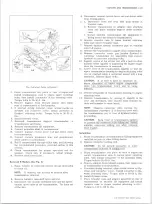
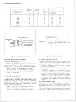
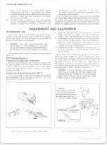
DIM. A
ALL EXCEPT
350 V8
.05
350 V8
.20
307 V-8 ENGINE
6 CYLINDER ENGINE
350
ENGINE
SWITCH
WITH ACCELERATOR CONTROLS
PROPERLY ADJUSTED, ROTATE
LEVER TO OBTAIN WIDE OPEN
THROTTLE. POSITION SWITCH TO
OBTAIN DIM. A SHOWN IN TABLE
BETWEEN PLUNGER AND LEVER.
TIGHTEN SWITCH ATTACHING
SCREWS.
Fig. 4T— Detent Switch Adjustment
5. Release the selector lever. The lever should now be
inhibited from engaging reverse range unless the
lever is lifted.
6. A properly adjusted linkage will prevent the selector
from moving beyond both the neutral detent, and the
drive detent unless the lever is lifted to pass over
the mechanical stop in the steering column.
7. In the event that an adjustment is required, place the
selector lever in drive (D) position as determined by
the transmission detent. See Steps 2 and 3.
8. Loosen the adjustment swivel at the mast jacket, and
rotate the transmission lever so that it contacts the
drive stop in the steering column.
9. Tighten the swivel and recheck the adjustment. See
Steps 2 and 6.
10. Readjust indicator needle if necessary to agree with
the transmission detent positions. See Section 9.
11. Readjust neutral safety switch if necessary to pro
vide the correct relationship to the transmission de
tent positions. See Section 12.
12. When properly adjusted the following conditions must
be met by manual operation of the steering column
shift lever.
a. From reverse to drive position travel, the trans
mission detent feel must be noted and related to
indicated position on dial.
b. When in drive and reverse positions, pull lever
rearward (towards steering wheel) and then re
lease. It must drop back into position with no
restrictions.
DETENT SWITCH ADJUSTMENT
Adjust Switch as Shown on Figure 4T
NEUTRAL SAFETY SWITCH ADJUSTMENT
The neutral safety switch must be adjusted so that the
car will start in the park or neutral position, but will
not start in the other positions. For replacement refer
to Section 12 of this manual.
D RAIN IN G A N D REFILLING TRANSMISSION
Drain oil immediately after operation before it has had
an opportunity to cool.
To drain oil proceed as follows:
10-30 CHEVROLET TRUCK SERVICE MANUAL
Содержание 10 1971 Series
Страница 1: ......
Страница 96: ......
Страница 100: ...10 30 CHEVROLET TRUCK SERVICE MANUAL Fig 4 10 30 Series Truck Frame FRAME 2 4 ...
Страница 120: ......
Страница 203: ...ENGINE 6 25 Fig 22L Engine Mounts 10 30 CHEVROLET TRUCK SERVICE MANUAL ...
Страница 215: ...ENGINE 6 37 REAR M O U NT Fig 21V Engine Mounts 10 30 CHEVROLET TRUCK SERVICE MANUAL ...
Страница 218: ......
Страница 249: ......
Страница 250: ...EMISSION CONTROL SYSTEMS 6T 4 Fig 3 Combination Emission Control System Routing V8 10 30 CHEVROLET TRUCK SERVICE MANUAL ...
Страница 324: ......
Страница 339: ...FUEL TANK AND EXHAUST SYSTEMS 8 15 SPECIAL TOOLS Fig 22 Special Tools 1 J 23346 Fuel Tank Gauge Remover and Installer ...
Страница 340: ......
Страница 365: ...10 30 CHEVROLET TRUCK SERVICE MANUAL Fig 43 Power Steering Pump M ounting STEERING 9 25 ...
Страница 368: ......
Страница 386: ......
Страница 390: ...ELECTRICAL BODY AND CHASSIS 12 4 10 30 CHEVROLET TRUCK SERVICE MANUAL ...
Страница 391: ......
Страница 392: ...ELECTRICAL BODY AND CHASSIS 12 6 Fig 5 Rear Lighting Composite 10 30 CHEVROLET TRUCK SERVICE MANUAL ...
Страница 409: ...ELECTRICAL BODY AND CHASSIS 12 23 Fig 27 Engine Compartment CA30 02 10 30 CHEVROLET TRUCK SERVICE MANUAL ...
Страница 410: ...ELECTRICAL BODY AND CHASSIS 12 24 18DK GRN 19 Fig 28 Instrument Panel CA30 02 10 30 CHEVROLET TRUCK SERVICE MANUAL ...
Страница 411: ...ELECTRICAL BODY AND CHASSIS 12 25 Fig 29 Instrument Panel CA30 02 10 30 CHEVROLET TRUCK SERVICE MANUAL ...
Страница 412: ...ELECTRICAL BODY AND CHASSIS 12 26 fh Ar r kk 4 Fig 30 Engine Compartment C A K A 10 20 CA30 03 z _ ...
Страница 416: ...ELECTRICAL BODY AND CHASSIS 12 30 Fig 34 Engine Compartment CA KA10 20 CA30 04 10 30 CHEVROLET TRUCK SERVICE MANUAL ...
Страница 420: ...ELECTRICAL BODY AND CHASSIS 12 34 Fig 38 Engine Compartment C A K A 1 0 20 06 16 10 30 CHEVROLET TRUCK SERVICE MANUAL ...
Страница 422: ...ELECTRICAL BODY AND CHASSIS 12 36 Fig 40 Instrument Panel C A K A 10 20 06 16 10 30 CHEVROLET TRUCK SERVICE MANUAL ...
Страница 423: ...ELECTRICAL BODY AND CHASSIS 12 37 Fig 41 R ear Lamps C A K A 1 0 20 06 16 10 30 CHEVROLET TRUCK SERVICE MANUAL ...
Страница 424: ...ELECTRICAL BODY AND CHASSIS 12 38 Fig 42 Engine Compartment CA KA10 20 CAl30 14 34 10 30 CHEVROLET TRUCK SERVICE MANUAL ...
Страница 426: ...ELECTRICAL BODY AND CHASSIS 12 40 Fig 44 Instrument Panel CA KA10 20 CA30 14 34 10 30 CHEVROLET TRUCK SERVICE MANUAL ...
Страница 428: ......
Страница 432: ......
Страница 449: ...SPECIFICATIONS 9 10 30 CHEVROLET TRUCK SERVICE MANUAL ...
Страница 463: ......
Страница 464: ......
Страница 465: ......
Страница 466: ......


