


STEERING 9-16
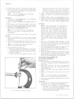
LO CK PLATE
Fig. 29— Removing Lock Plate Assembly
plate and the instrument panel seal from the col
umn jacket.
Assembly— Tilt Columns
NOTE:
When lubricating components during
the following installation sequence, use a gen
eral purpose lithium soap grease.
1. Install the dash panel seal, mounting plate and the
instrument panel seal on the column.
2. Column Shift Models - Press a new shift lever
spring into the shift lever housing.
3. Slide the shift lever housing over the upper end of the
column.
4. Place the wave washer and lock plate in position.
Work the lock plate into the notches by tipping the
plate toward the housing (compressing the wave
washer) at the open side of the column. Lubricate
the lock plate and upper end of the shift tube.
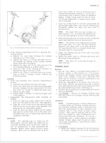
5. Carefully install the shift tube into the lower end of
the column (make sure the foam seal is at the lower
end of the shift tube). Align the keyway in the tube
with the key in the shift lever housing and complete
installation of the shift tube using Tool J-22549
(fig. 30). The shift lever housing key must bottom in
the shift tube slot to be fully installed. Remove
Tool J-22549 from the column. Lubricate and push
foam seal in flush with column housing.
CAUTION:
Do Not hammer or force the tube
when installing in the column.
6. Pull up on the shift lever housing (to compress the
wave washer) and install the thrust washer and re
taining ring. Be sure the ring is seated in both
slots of the shift tube.
7. Lubricate the I.D. of the bearing housing support and
install the support, aligning the bolt holes in the
support with the bolt holes in the lock plate. Install
the four support screws and torque to 45 in. lbs.
8. Assemble the steering shaft as follows:
a. Lubricate and assemble the centering spheres
and preload spring.
Fig. 30— Installing Shift Pin Tube
b. Install the spheres into the upper (short) shaft
and rotate 90°.
c. Install the lower shaft 90° to the upper shaft and
over the centering spheres. Slowly straighten
the shafts while compressing the preload spring.
9. Install the shaft assembly into the housing from the
upper end.
10. Install the lower bearing and adapter, bearing re
inforcement, wire clip, pot joint coupling and lower
shaft
as
described
u n d e r
"Lower Bearing
Installation".
11. Assemble the bearing housing as follows:
a. Press the new upper and lower bearing races
into the bearing housing.
b. Lubricate and install the bearings into the bear
ing races.
c. Place the lock shoe springs in position in the
housing. Install each shoe in place and compress
the spring until a suitable size straight punch
can be used to hold the shoes in position (it may
be necessary to acquire assistance to install the
shoes). Once the shoes are in place, drive in the
shoe retaining pin.
d. Install the shoe release lever and drive in the
pivot pin.
e. Install the tilt release lever.
f. Lubricate the shoes and release lever.
12. Install the bearing housing assembly to the support.
Hold the tilt release lever in the "up" position until
the shoes have fully engaged the support. Lubricate
and install the bearing housing pivot pins. Press
the pins in flush with the housing.
13. Place the housing in the full "up” position and then
install tilt spring and retainer (tapered end of spring
first). Push into the housing approximately 3/16"
and rotate counter clockwise 1/8 turn.
14. Lubricate and install the upper bearing upper race,
race seat and locknut. Tighten the locknut (using
Socket J-22599) until the torque required to rotate
steering shaft is 15 in. oz. (column must be in
straight-ahead position).
15. Remove the tilt release lever.
10-30 CHEVROLET TRUCK SERVICE MANUAL
Содержание 10 1971 Series
Страница 1: ......
Страница 96: ......
Страница 100: ...10 30 CHEVROLET TRUCK SERVICE MANUAL Fig 4 10 30 Series Truck Frame FRAME 2 4 ...
Страница 120: ......
Страница 203: ...ENGINE 6 25 Fig 22L Engine Mounts 10 30 CHEVROLET TRUCK SERVICE MANUAL ...
Страница 215: ...ENGINE 6 37 REAR M O U NT Fig 21V Engine Mounts 10 30 CHEVROLET TRUCK SERVICE MANUAL ...
Страница 218: ......
Страница 249: ......
Страница 250: ...EMISSION CONTROL SYSTEMS 6T 4 Fig 3 Combination Emission Control System Routing V8 10 30 CHEVROLET TRUCK SERVICE MANUAL ...
Страница 324: ......
Страница 339: ...FUEL TANK AND EXHAUST SYSTEMS 8 15 SPECIAL TOOLS Fig 22 Special Tools 1 J 23346 Fuel Tank Gauge Remover and Installer ...
Страница 340: ......
Страница 365: ...10 30 CHEVROLET TRUCK SERVICE MANUAL Fig 43 Power Steering Pump M ounting STEERING 9 25 ...
Страница 368: ......
Страница 386: ......
Страница 390: ...ELECTRICAL BODY AND CHASSIS 12 4 10 30 CHEVROLET TRUCK SERVICE MANUAL ...
Страница 391: ......
Страница 392: ...ELECTRICAL BODY AND CHASSIS 12 6 Fig 5 Rear Lighting Composite 10 30 CHEVROLET TRUCK SERVICE MANUAL ...
Страница 409: ...ELECTRICAL BODY AND CHASSIS 12 23 Fig 27 Engine Compartment CA30 02 10 30 CHEVROLET TRUCK SERVICE MANUAL ...
Страница 410: ...ELECTRICAL BODY AND CHASSIS 12 24 18DK GRN 19 Fig 28 Instrument Panel CA30 02 10 30 CHEVROLET TRUCK SERVICE MANUAL ...
Страница 411: ...ELECTRICAL BODY AND CHASSIS 12 25 Fig 29 Instrument Panel CA30 02 10 30 CHEVROLET TRUCK SERVICE MANUAL ...
Страница 412: ...ELECTRICAL BODY AND CHASSIS 12 26 fh Ar r kk 4 Fig 30 Engine Compartment C A K A 10 20 CA30 03 z _ ...
Страница 416: ...ELECTRICAL BODY AND CHASSIS 12 30 Fig 34 Engine Compartment CA KA10 20 CA30 04 10 30 CHEVROLET TRUCK SERVICE MANUAL ...
Страница 420: ...ELECTRICAL BODY AND CHASSIS 12 34 Fig 38 Engine Compartment C A K A 1 0 20 06 16 10 30 CHEVROLET TRUCK SERVICE MANUAL ...
Страница 422: ...ELECTRICAL BODY AND CHASSIS 12 36 Fig 40 Instrument Panel C A K A 10 20 06 16 10 30 CHEVROLET TRUCK SERVICE MANUAL ...
Страница 423: ...ELECTRICAL BODY AND CHASSIS 12 37 Fig 41 R ear Lamps C A K A 1 0 20 06 16 10 30 CHEVROLET TRUCK SERVICE MANUAL ...
Страница 424: ...ELECTRICAL BODY AND CHASSIS 12 38 Fig 42 Engine Compartment CA KA10 20 CAl30 14 34 10 30 CHEVROLET TRUCK SERVICE MANUAL ...
Страница 426: ...ELECTRICAL BODY AND CHASSIS 12 40 Fig 44 Instrument Panel CA KA10 20 CA30 14 34 10 30 CHEVROLET TRUCK SERVICE MANUAL ...
Страница 428: ......
Страница 432: ......
Страница 449: ...SPECIFICATIONS 9 10 30 CHEVROLET TRUCK SERVICE MANUAL ...
Страница 463: ......
Страница 464: ......
Страница 465: ......
Страница 466: ......


