


ENGINE-ELECTRICAL 6Y-16
NOTE:
The contact point pressure must fall
within specified limits. Weak tension will cause
chatter resulting in arching and burning of the
points and an ignition miss at high speed, while
excessive tension will cause undue wear of the
contact points, cam and rubbing block. Breaker
arm spring tension should be 19-23 ounces. The
contact point pressure should be checked with a
spring gauge. The scale should be hooked to the
breaker lever and the pull exerted at 90 degrees
to the breaker lever as shown in Figure 2i. The
reading should be taken just as the points sepa
rate. The pressure can be adjusted by bending
the breaker lever spring. If the pressure is
excessive, it can be decreased by pinching the
spring carefully. To increase pressure, the lever
must be removed from the distributor so the
spring can be bent away from the lever. Avoid
excessive spring distortion.
9. Set point opening (.019" for new points).
10. Reinstall dust shield, rotor, position and lock distri
butor cap to housing.
11. Start engine and test dwell and ignition timing.
Eight Cylinder Engine Distributor
1. The contact point set is replaced as one complete
assembly and only dwell angle requires adjustment
after replacement. Breaker leaver spring tension and
point alignment are factory set.
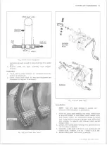
2. Remove the distributor cap by placing a screw driver
in the slot head of the latach, press down and turn
1/4 turn in either direction.
3. Remove the two attaching screws which hold the base
of the contact set assembly in place.
4. Remove the primary and condenser leads from their
nylon insulated connection (fig. 3i) in contact set.
5. Reverse Steps 2, 3 and 4 to install new contact set.
CAUTION:
install the primary and condenser
leads as shown in Figure 3i. Improper installa
tion will cause lead interference between the cap,
weight base and breaker advance plate.
6. If vehicle has 20,000 to 25,000 miles (or sooner if
desired) the cam lubricator wick (fig. 4i) should be
changed. Using long nosed pliers squeeze assembly
together at base and lift out. Remove all old lubri
cant from cam surface. Replace in same manner.
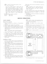
NOTE:
End of cam lubricant wick should be
adjusted to just touch cam lobes. Over lubrica
tion of cam resulting in grease on contact points
can be caused by cam lubrication wick bearing
too hard against cam surface. A correctly ad
justed cam lubricator wick will provide adequate
lubrication for cam. Do not apply additional
grease to cam surface.
7. Start engine and check point dwell and ignition timing.
Setting Dwell Angle
Six Cylinder Engine Distributor
The point opening of new points can be checked with a
feeeler gauge, but the use of a feeler gauge on rough or
uncleaned used points is not recommended since accurate
mechanical gauging cannot be done on such points (fig 6i).
Contacts points must be set to the proper opening.
Points set too close may tend to burn and pit rapidly.
Points with excessive separation tend to cause a weak
spark at high speed. Proper point setting for all models
are:
.019" for new points
.016" for used points
New points must be set to the larger opening as the
rubbing block will wear down slightly while seating to the
cam. Contact points should be cleaned before adjusting if
they have been in service.
To adjust the contact point opening:
1. If necessary, align points (fig. 6i) by bending the fixed
contact support. Do not bend the breaker lever. Do
not attempt to align used points; replace them where
serious misalignment is observed. Use an aligning
tool if available.
2. Turn or crank the distributor shaft until the breaker
Fig. 2 i-C h e c k in g Breaker Arm Spring Tension
10-30 CHEVROLET TRUCK SERVICE MANUAL
Содержание 10 1971 Series
Страница 1: ......
Страница 96: ......
Страница 100: ...10 30 CHEVROLET TRUCK SERVICE MANUAL Fig 4 10 30 Series Truck Frame FRAME 2 4 ...
Страница 120: ......
Страница 203: ...ENGINE 6 25 Fig 22L Engine Mounts 10 30 CHEVROLET TRUCK SERVICE MANUAL ...
Страница 215: ...ENGINE 6 37 REAR M O U NT Fig 21V Engine Mounts 10 30 CHEVROLET TRUCK SERVICE MANUAL ...
Страница 218: ......
Страница 249: ......
Страница 250: ...EMISSION CONTROL SYSTEMS 6T 4 Fig 3 Combination Emission Control System Routing V8 10 30 CHEVROLET TRUCK SERVICE MANUAL ...
Страница 324: ......
Страница 339: ...FUEL TANK AND EXHAUST SYSTEMS 8 15 SPECIAL TOOLS Fig 22 Special Tools 1 J 23346 Fuel Tank Gauge Remover and Installer ...
Страница 340: ......
Страница 365: ...10 30 CHEVROLET TRUCK SERVICE MANUAL Fig 43 Power Steering Pump M ounting STEERING 9 25 ...
Страница 368: ......
Страница 386: ......
Страница 390: ...ELECTRICAL BODY AND CHASSIS 12 4 10 30 CHEVROLET TRUCK SERVICE MANUAL ...
Страница 391: ......
Страница 392: ...ELECTRICAL BODY AND CHASSIS 12 6 Fig 5 Rear Lighting Composite 10 30 CHEVROLET TRUCK SERVICE MANUAL ...
Страница 409: ...ELECTRICAL BODY AND CHASSIS 12 23 Fig 27 Engine Compartment CA30 02 10 30 CHEVROLET TRUCK SERVICE MANUAL ...
Страница 410: ...ELECTRICAL BODY AND CHASSIS 12 24 18DK GRN 19 Fig 28 Instrument Panel CA30 02 10 30 CHEVROLET TRUCK SERVICE MANUAL ...
Страница 411: ...ELECTRICAL BODY AND CHASSIS 12 25 Fig 29 Instrument Panel CA30 02 10 30 CHEVROLET TRUCK SERVICE MANUAL ...
Страница 412: ...ELECTRICAL BODY AND CHASSIS 12 26 fh Ar r kk 4 Fig 30 Engine Compartment C A K A 10 20 CA30 03 z _ ...
Страница 416: ...ELECTRICAL BODY AND CHASSIS 12 30 Fig 34 Engine Compartment CA KA10 20 CA30 04 10 30 CHEVROLET TRUCK SERVICE MANUAL ...
Страница 420: ...ELECTRICAL BODY AND CHASSIS 12 34 Fig 38 Engine Compartment C A K A 1 0 20 06 16 10 30 CHEVROLET TRUCK SERVICE MANUAL ...
Страница 422: ...ELECTRICAL BODY AND CHASSIS 12 36 Fig 40 Instrument Panel C A K A 10 20 06 16 10 30 CHEVROLET TRUCK SERVICE MANUAL ...
Страница 423: ...ELECTRICAL BODY AND CHASSIS 12 37 Fig 41 R ear Lamps C A K A 1 0 20 06 16 10 30 CHEVROLET TRUCK SERVICE MANUAL ...
Страница 424: ...ELECTRICAL BODY AND CHASSIS 12 38 Fig 42 Engine Compartment CA KA10 20 CAl30 14 34 10 30 CHEVROLET TRUCK SERVICE MANUAL ...
Страница 426: ...ELECTRICAL BODY AND CHASSIS 12 40 Fig 44 Instrument Panel CA KA10 20 CA30 14 34 10 30 CHEVROLET TRUCK SERVICE MANUAL ...
Страница 428: ......
Страница 432: ......
Страница 449: ...SPECIFICATIONS 9 10 30 CHEVROLET TRUCK SERVICE MANUAL ...
Страница 463: ......
Страница 464: ......
Страница 465: ......
Страница 466: ......


