


ENGINE 6-30
b. In rare cases, the ball itself may be out-of-round
or have a flat spot.
c. Improper adjustment.
In most cases where noise exists in one or more lifters
all lifter units should be removed, disassembled, cleaned
in a solvent, reassembled, and reinstalled in the engine.
If dirt, corrosion, carbon, etc. is shown to exist in one
unit, it more likely exists in all the units, thus it would
only be a matter of time before all lifters caused trouble.
Removal
1. Remove intake manifold as outlined.
2. Remove valve mechanism as outlined.
3. Remove valve lifters.
NOTE:
Place valve lifters in a rack so they
may be reinstalled in the same location.
Installation
1. Install valve lifters.
NOTE:
Whenever new valve lifters are being
installed, polish lifter first with #600 wet/dry
emery paper and coat foot of valve lifters with
“ Molykote” or its equivalent.
2. Install intake manifold as outlined.
3. Install and adjust valve mechanism as outlined.
Valve Stem Oil Seal and/or Valve Spring
Replacement
1. Remove rocker arm cover as outlined.
2. Remove spark plug, rocker arm and push rod on the
cylinder(s) to be serviced.
3. Install air line adapter Tool J-23590 to spark plug
port and apply compressed air to hold the valves in
place.
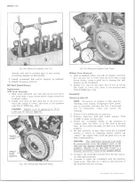
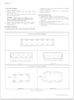
4. Using Tool J-5892 to compress the valve spring,
remove the valve locks, valve cap and valve spring
and damper (fig. 3V).
5. Remove the valve stem oil seal.
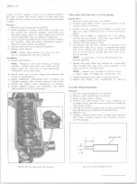
Fig. 2 V -V a lv e Adjustment
6. Assemble as follows:
Small V8 Engines
a. Set the valve spring and damper, valve shield and
valve cap in place. Compress the spring with Tool
J-5892 and install oil seal in the lower groove of
the stem, making sure the seal is flat and not
twisted.
NOTE:
A light coat of oil on the seal will help
prevent twisting.
b. Install the valve locks and release the com
pressor tool making sure the locks seat properly
in the upper groove of the valve stem.
NOTE:
Grease may be used to hold the locks in
place while releasing the compressor tool.
Mark IV V8 Engines
a., Install new valve stem oil seal (coated with oil)
in position over valve guide.
b. Set the valve spring and damper and valve cap
in place.
c. Compress the spring with Tool J-5892 and install
the valve locks then release the compressor tool,
making sure the locks seat properly in the groove
of the valve stem.
NOTE:
Grease may be used to hold the locks
in place while releasing the compressor tool.
7. Install spark plug and torque to specifications.
8. Install and adjust valve mechanism as outlined.
Cylinder Head Assembly
Removal
1. Remove intake manifold as outlined.
Fig. 3V — Compressing V a lv e Spring
10-30 CHEVROLET TRUCK SERVICE MANUAL
Содержание 10 1971 Series
Страница 1: ......
Страница 96: ......
Страница 100: ...10 30 CHEVROLET TRUCK SERVICE MANUAL Fig 4 10 30 Series Truck Frame FRAME 2 4 ...
Страница 120: ......
Страница 203: ...ENGINE 6 25 Fig 22L Engine Mounts 10 30 CHEVROLET TRUCK SERVICE MANUAL ...
Страница 215: ...ENGINE 6 37 REAR M O U NT Fig 21V Engine Mounts 10 30 CHEVROLET TRUCK SERVICE MANUAL ...
Страница 218: ......
Страница 249: ......
Страница 250: ...EMISSION CONTROL SYSTEMS 6T 4 Fig 3 Combination Emission Control System Routing V8 10 30 CHEVROLET TRUCK SERVICE MANUAL ...
Страница 324: ......
Страница 339: ...FUEL TANK AND EXHAUST SYSTEMS 8 15 SPECIAL TOOLS Fig 22 Special Tools 1 J 23346 Fuel Tank Gauge Remover and Installer ...
Страница 340: ......
Страница 365: ...10 30 CHEVROLET TRUCK SERVICE MANUAL Fig 43 Power Steering Pump M ounting STEERING 9 25 ...
Страница 368: ......
Страница 386: ......
Страница 390: ...ELECTRICAL BODY AND CHASSIS 12 4 10 30 CHEVROLET TRUCK SERVICE MANUAL ...
Страница 391: ......
Страница 392: ...ELECTRICAL BODY AND CHASSIS 12 6 Fig 5 Rear Lighting Composite 10 30 CHEVROLET TRUCK SERVICE MANUAL ...
Страница 409: ...ELECTRICAL BODY AND CHASSIS 12 23 Fig 27 Engine Compartment CA30 02 10 30 CHEVROLET TRUCK SERVICE MANUAL ...
Страница 410: ...ELECTRICAL BODY AND CHASSIS 12 24 18DK GRN 19 Fig 28 Instrument Panel CA30 02 10 30 CHEVROLET TRUCK SERVICE MANUAL ...
Страница 411: ...ELECTRICAL BODY AND CHASSIS 12 25 Fig 29 Instrument Panel CA30 02 10 30 CHEVROLET TRUCK SERVICE MANUAL ...
Страница 412: ...ELECTRICAL BODY AND CHASSIS 12 26 fh Ar r kk 4 Fig 30 Engine Compartment C A K A 10 20 CA30 03 z _ ...
Страница 416: ...ELECTRICAL BODY AND CHASSIS 12 30 Fig 34 Engine Compartment CA KA10 20 CA30 04 10 30 CHEVROLET TRUCK SERVICE MANUAL ...
Страница 420: ...ELECTRICAL BODY AND CHASSIS 12 34 Fig 38 Engine Compartment C A K A 1 0 20 06 16 10 30 CHEVROLET TRUCK SERVICE MANUAL ...
Страница 422: ...ELECTRICAL BODY AND CHASSIS 12 36 Fig 40 Instrument Panel C A K A 10 20 06 16 10 30 CHEVROLET TRUCK SERVICE MANUAL ...
Страница 423: ...ELECTRICAL BODY AND CHASSIS 12 37 Fig 41 R ear Lamps C A K A 1 0 20 06 16 10 30 CHEVROLET TRUCK SERVICE MANUAL ...
Страница 424: ...ELECTRICAL BODY AND CHASSIS 12 38 Fig 42 Engine Compartment CA KA10 20 CAl30 14 34 10 30 CHEVROLET TRUCK SERVICE MANUAL ...
Страница 426: ...ELECTRICAL BODY AND CHASSIS 12 40 Fig 44 Instrument Panel CA KA10 20 CA30 14 34 10 30 CHEVROLET TRUCK SERVICE MANUAL ...
Страница 428: ......
Страница 432: ......
Страница 449: ...SPECIFICATIONS 9 10 30 CHEVROLET TRUCK SERVICE MANUAL ...
Страница 463: ......
Страница 464: ......
Страница 465: ......
Страница 466: ......


