


BODY 1-31
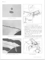
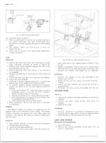
Fig. 78— Tapping Stationary Glass into Weatherstrip
8. Install heavy rubber wedge between run channel and
inside edge of weatherstrip from front edge of sta
tionary glass at top around to front edge at bottom.
The round edge enters the rubber and the ribbed side
goes next to the run channel.
9.
Install center weatherstrip on front edge of station
ary glass with plush side next to sliding glass. Ap
ply
3 - M
Weatherstrip Adhesive, or its equivalent, to
the inside of this channel before installing. Pushing
each end of weatherstrip on before pushing up the
center will eliminate the ends catching in the rubber
and give it a crowding effect at top and bottom for
tighter seal.
10.
Feed one end of weatherstrip filler into handle of
special Tool
J -2 1 8 9
and out through the end which
spreads the weatherstrip channel.
11.
Starting at bottom center, insert the end of the tool
and end of filler in channel, tapered part of the filler
toward the glass.
12.
While holding the tool firmly, with spreading end in
channel, follow around the channel spreading it open
and feeding the filler into the opening around the
entire weatherstrip. With the flat side of common
screw driver placed against the starting end of the
insert filler drive filler back an inch or two. Cut
off the other end to make snug joint and work into
channel. This prevents separation at joint after
window has been in service.
13.
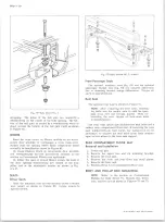
The run channel at front of window should be opened
up to allow for the extra thickness of the glass thumb
pull. Use a block of wood slightly wider than chan
nel and with one edge rounded smooth so as not to
damage channel drive it in spreading the area around
the thumb pull until glass enters channel with rea
sonable ease.
14. Install sliding window lock keeper on front edge of
door. With window pushed forward in closed posi
tion, place keeper behind lock plunger and attach to
door with sheet metal screws. To release window
pull out on knob and back on glass pull.
15. Locate (3) holes equally spaced across bottom of
window rubber on the outside. Keep holes in straight
part of rubber. Using 1/4" diameter drill bit start
holes 1/2 inch below top edge of rubber and drill up
through bottom side of run channel providing holes
for water to drain out of channel.
16. Place metal channel over leading edge of weather
strip with the short leg of channel on the plush side
of weatherstrip and tap on with rubber mallet. In
stall stationary glass retainer clips at top and bot
tom of center weatherstrip. Please note that there
is a difference between top and bottom clips. It is
important that they be installed correctly. Without
these clips the impact of closing door will drive the
stationary glass forward and out of the rubber at
rear of window.
DRIVER’S W IN D O W SLIDING GLASS
Replacement
1. Using a pointed tool, raise one end of the weather
strip filler until it is far enough out to take hold of
by hand. Then pull filler out of its channel all
around the window.
2. Using a pointed tool, raise one end of heavy rubber
wedge in front of stationary glass until it can be
grasped by hand. Pull entire wedge off its channel.
3. Pull stationary rear glass forward until it is out of
rubber at the rear.
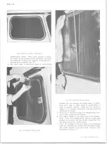
4. Using special wire hook, furnished with Body Weath-
erstripping Tool Set (J-2189) or similar tool, work
top of glass out of rubber and lift out of window.
5. If sliding glass is still intact, slide glass back until
front edge at top is back of joint in weatherstrip
rubber. Using the paint scraper or similar object,
slip blade between channel and glass at top. Lift
up on scraper to work glass out of channel.
6. If sliding glass is already out and there is no damage
to the weatherstrip rubber or the glass run channel
then you are ready to install a new sliding glass.
7. To install the sliding glass follow the instructions
and illustrations under "Complete Driver's Window
Installation.” Begin with operation 3 and continue
through operation 12. Continue through to operation
15 if new weatherstrip has been used.
DRIVER’S W IN D O W STATIONARY GLASS
Replacement
1. Follow operations 1 through 4 under Driver's Window
sliding Glass Replacement. If glass is completely
gone and there is no further damage to the window,
operations 1 and 2 will prepare the window for sta
tionary glass replacement.
2. To install the new glass follow the instruction set
forth for “ Complete Driver's Window Installation."
10-30 CHEVROLET TRUCK SERVICE MANUAL
Содержание 10 1971 Series
Страница 1: ......
Страница 96: ......
Страница 100: ...10 30 CHEVROLET TRUCK SERVICE MANUAL Fig 4 10 30 Series Truck Frame FRAME 2 4 ...
Страница 120: ......
Страница 203: ...ENGINE 6 25 Fig 22L Engine Mounts 10 30 CHEVROLET TRUCK SERVICE MANUAL ...
Страница 215: ...ENGINE 6 37 REAR M O U NT Fig 21V Engine Mounts 10 30 CHEVROLET TRUCK SERVICE MANUAL ...
Страница 218: ......
Страница 249: ......
Страница 250: ...EMISSION CONTROL SYSTEMS 6T 4 Fig 3 Combination Emission Control System Routing V8 10 30 CHEVROLET TRUCK SERVICE MANUAL ...
Страница 324: ......
Страница 339: ...FUEL TANK AND EXHAUST SYSTEMS 8 15 SPECIAL TOOLS Fig 22 Special Tools 1 J 23346 Fuel Tank Gauge Remover and Installer ...
Страница 340: ......
Страница 365: ...10 30 CHEVROLET TRUCK SERVICE MANUAL Fig 43 Power Steering Pump M ounting STEERING 9 25 ...
Страница 368: ......
Страница 386: ......
Страница 390: ...ELECTRICAL BODY AND CHASSIS 12 4 10 30 CHEVROLET TRUCK SERVICE MANUAL ...
Страница 391: ......
Страница 392: ...ELECTRICAL BODY AND CHASSIS 12 6 Fig 5 Rear Lighting Composite 10 30 CHEVROLET TRUCK SERVICE MANUAL ...
Страница 409: ...ELECTRICAL BODY AND CHASSIS 12 23 Fig 27 Engine Compartment CA30 02 10 30 CHEVROLET TRUCK SERVICE MANUAL ...
Страница 410: ...ELECTRICAL BODY AND CHASSIS 12 24 18DK GRN 19 Fig 28 Instrument Panel CA30 02 10 30 CHEVROLET TRUCK SERVICE MANUAL ...
Страница 411: ...ELECTRICAL BODY AND CHASSIS 12 25 Fig 29 Instrument Panel CA30 02 10 30 CHEVROLET TRUCK SERVICE MANUAL ...
Страница 412: ...ELECTRICAL BODY AND CHASSIS 12 26 fh Ar r kk 4 Fig 30 Engine Compartment C A K A 10 20 CA30 03 z _ ...
Страница 416: ...ELECTRICAL BODY AND CHASSIS 12 30 Fig 34 Engine Compartment CA KA10 20 CA30 04 10 30 CHEVROLET TRUCK SERVICE MANUAL ...
Страница 420: ...ELECTRICAL BODY AND CHASSIS 12 34 Fig 38 Engine Compartment C A K A 1 0 20 06 16 10 30 CHEVROLET TRUCK SERVICE MANUAL ...
Страница 422: ...ELECTRICAL BODY AND CHASSIS 12 36 Fig 40 Instrument Panel C A K A 10 20 06 16 10 30 CHEVROLET TRUCK SERVICE MANUAL ...
Страница 423: ...ELECTRICAL BODY AND CHASSIS 12 37 Fig 41 R ear Lamps C A K A 1 0 20 06 16 10 30 CHEVROLET TRUCK SERVICE MANUAL ...
Страница 424: ...ELECTRICAL BODY AND CHASSIS 12 38 Fig 42 Engine Compartment CA KA10 20 CAl30 14 34 10 30 CHEVROLET TRUCK SERVICE MANUAL ...
Страница 426: ...ELECTRICAL BODY AND CHASSIS 12 40 Fig 44 Instrument Panel CA KA10 20 CA30 14 34 10 30 CHEVROLET TRUCK SERVICE MANUAL ...
Страница 428: ......
Страница 432: ......
Страница 449: ...SPECIFICATIONS 9 10 30 CHEVROLET TRUCK SERVICE MANUAL ...
Страница 463: ......
Страница 464: ......
Страница 465: ......
Страница 466: ......