


REAR SUSPENSION AND DRIVE LINE 4-16
Fig. 30— A xle Vent Installation
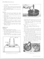
2. Connect and secure shock absorbers to axle
brackets.
3. Connect hydraulic brake hose to connector on axle
housing, and bleed hydraulic system as specified in
Section 5. (If vehicle is equipped with air brakes,
connect air line at brake chambers--test connections
to make sure that there is no leakage.)
4. Connect hand brake cables and adjust parking brakes
as specified in Section 5.
5. Reassemble the rear universal joint, making sure
that "U ” bolts are drawn up tight and locked prop
erly. Caution should be taken not to overtighten
bolt nuts and cause bearing cups to become distorted.
6. Install rear wheels, remove stand jacks, and lower
vehicle.
7. Test operation of brakes and rear axle.
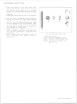
3.
Thoroughly clean both the axle shaft flange and the
end of the wheel hub.
NOTE:
Any lubricant on these surfaces tends
to loosen axle shaft flange bolts.
4.
Place a new gasket over the axle shaft and position
the axle shaft in the housing so that the shaft splines
enter the differential side gear. Position gasket so
that holes are in alignment and install flange-to-hub
attaching bolts--torque bolts to specifications.
NOTE:
To prevent lubricant from leaking
through flange holes, apply a non-hardening
sealer (such as Permatex Type A or equivalent)
to bolt threads. Use care in the amount of sealer
applied, as in too heavy an application, the
sealer may be forced out as the bolt is installed
and may destroy sealing effect of the flange-to-
hub gasket.
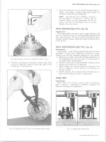
AXLE SHAFT 11,000 LB. AXLES
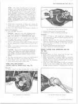
AXLE VENT
Replacement
Service replacement axle housing assemblies are not
equipped with an axle vent; therefore, always make sure
that a new vent assembly is installed when replacing the
housing. If axle vent requires replacement, pry old vent
from housing being sure that entire vent is removed.
Prick punch around carrier hole to insure fit of replace
ment vent. Tap new vent into housing using a soft-faced
hammer. Vent should be positioned in housing so that
flat surface is toward centerline of differential carrier
(fig. 30).
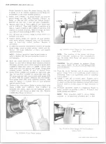
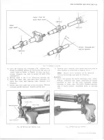
AXLE SHAFT (EXCEPT 11,000 LB. AXLE)
Removal and Installation
1. Remove bolts and lock washers that attach the axle
shaft flange to the wheel hub.
2. Install two 1/2"-13 bolts in the threaded holes pro
vided in the axle shaft flange. By turning these bolts
alternately the axle shaft may be easily started and
then removed from the housing (fig. 31).
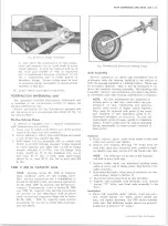
Fig. 32— Removing A xle Shaft (11,000 lb. A xle )
10-30 CHEVROLET TRUCK SERVICE MANUAL
Fig. 31.— Removing A xle Shaft (5200 and 7200 lb. Axle)
Removal and Installation
1. Remove hub cap, and install Tool J-8117 in tapped
hole on shaft flange.
2. Install slide hammer (Tool J-2619) and remove axle
shaft (fig. 32).
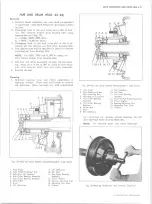
3. Thoroughly remove old gasket material from hub and
hub cap. Clean shaft flange and mating surfaces in
the wheel hub.
4. Install axle shaft so that the flange splines index into
hub splines. Tap shaft into position, using J-8117
and J-2619.
5. Install new hub cap-to-hub gasket, position hub cap to
hub and install attaching bolts--torque bolts to
specifications.
Содержание 10 1971 Series
Страница 1: ......
Страница 96: ......
Страница 100: ...10 30 CHEVROLET TRUCK SERVICE MANUAL Fig 4 10 30 Series Truck Frame FRAME 2 4 ...
Страница 120: ......
Страница 203: ...ENGINE 6 25 Fig 22L Engine Mounts 10 30 CHEVROLET TRUCK SERVICE MANUAL ...
Страница 215: ...ENGINE 6 37 REAR M O U NT Fig 21V Engine Mounts 10 30 CHEVROLET TRUCK SERVICE MANUAL ...
Страница 218: ......
Страница 249: ......
Страница 250: ...EMISSION CONTROL SYSTEMS 6T 4 Fig 3 Combination Emission Control System Routing V8 10 30 CHEVROLET TRUCK SERVICE MANUAL ...
Страница 324: ......
Страница 339: ...FUEL TANK AND EXHAUST SYSTEMS 8 15 SPECIAL TOOLS Fig 22 Special Tools 1 J 23346 Fuel Tank Gauge Remover and Installer ...
Страница 340: ......
Страница 365: ...10 30 CHEVROLET TRUCK SERVICE MANUAL Fig 43 Power Steering Pump M ounting STEERING 9 25 ...
Страница 368: ......
Страница 386: ......
Страница 390: ...ELECTRICAL BODY AND CHASSIS 12 4 10 30 CHEVROLET TRUCK SERVICE MANUAL ...
Страница 391: ......
Страница 392: ...ELECTRICAL BODY AND CHASSIS 12 6 Fig 5 Rear Lighting Composite 10 30 CHEVROLET TRUCK SERVICE MANUAL ...
Страница 409: ...ELECTRICAL BODY AND CHASSIS 12 23 Fig 27 Engine Compartment CA30 02 10 30 CHEVROLET TRUCK SERVICE MANUAL ...
Страница 410: ...ELECTRICAL BODY AND CHASSIS 12 24 18DK GRN 19 Fig 28 Instrument Panel CA30 02 10 30 CHEVROLET TRUCK SERVICE MANUAL ...
Страница 411: ...ELECTRICAL BODY AND CHASSIS 12 25 Fig 29 Instrument Panel CA30 02 10 30 CHEVROLET TRUCK SERVICE MANUAL ...
Страница 412: ...ELECTRICAL BODY AND CHASSIS 12 26 fh Ar r kk 4 Fig 30 Engine Compartment C A K A 10 20 CA30 03 z _ ...
Страница 416: ...ELECTRICAL BODY AND CHASSIS 12 30 Fig 34 Engine Compartment CA KA10 20 CA30 04 10 30 CHEVROLET TRUCK SERVICE MANUAL ...
Страница 420: ...ELECTRICAL BODY AND CHASSIS 12 34 Fig 38 Engine Compartment C A K A 1 0 20 06 16 10 30 CHEVROLET TRUCK SERVICE MANUAL ...
Страница 422: ...ELECTRICAL BODY AND CHASSIS 12 36 Fig 40 Instrument Panel C A K A 10 20 06 16 10 30 CHEVROLET TRUCK SERVICE MANUAL ...
Страница 423: ...ELECTRICAL BODY AND CHASSIS 12 37 Fig 41 R ear Lamps C A K A 1 0 20 06 16 10 30 CHEVROLET TRUCK SERVICE MANUAL ...
Страница 424: ...ELECTRICAL BODY AND CHASSIS 12 38 Fig 42 Engine Compartment CA KA10 20 CAl30 14 34 10 30 CHEVROLET TRUCK SERVICE MANUAL ...
Страница 426: ...ELECTRICAL BODY AND CHASSIS 12 40 Fig 44 Instrument Panel CA KA10 20 CA30 14 34 10 30 CHEVROLET TRUCK SERVICE MANUAL ...
Страница 428: ......
Страница 432: ......
Страница 449: ...SPECIFICATIONS 9 10 30 CHEVROLET TRUCK SERVICE MANUAL ...
Страница 463: ......
Страница 464: ......
Страница 465: ......
Страница 466: ......


