


STEERING 9-15
SHIFT TUBE-
R E TA IN IN G RING
1/16” 45° CH A M F ER
R EM O V E DOTTED
PO R T IO N
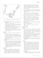
Fig. 27— Revised Shi ft Tube Removing Tool J-22551
Fig. 26— Removing Shift Tube Retaining Ring
centering spheres and preload spring from the
upper shaft.
10. Remove the four bearing housing support screws
and remove the support.
Column Shift Models - If the shift tube index plate
must be removed, remove the two retaining screws
and remove the plate.
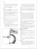
11. Remove the shift tube retaining ring with a screw
driver (fig. 26). Remove the thrust washer.
12. Remove the neutral-safety or back-up lamp switch
screws and remove the switch.
13. Rework Shift Tube Removing Tool J-22551 by re
moving 1/2" from the pilot end of the tool (fig. 27).
This allows the shift tube to be pushed further out of
the housing and will not affect the use of the tool on
passenger car columns.
14. Remove the shift tube assembly using Tool J-22551
(fig. 28). Insert the hooked end of the tool into the
notch in the shift tube just below the shift lever
housing key. Pilot the sleeve over the threaded end
of the tool and into the upper end of the shift tube.
Force the shift tube out of the housing by turning
the nut onto the tool. If the shift tube is not com
pletely free when the nut is bottomed on the threads,
complete the removal by hand.
CAUTION:
Do Not hammer or pull on the
shift tube during removal. On column shift
models, guide the lower shift lever through the
slotted opening in the column to prevent damage
to the tube or column.
15. Remove the lock plate by sliding out of the column
notches, tipping the plate downward toward the hous
ing (to compress the wave washer) and then re
moving as shown in Figure 29. Remove the wave
washer.
16. Remove the shift lever housing.
17. Column Shift Models - Remove the shift lever spring
by winding the spring up with pliers.
18. If necessary, remove the dash panel seal, mounting
H O O K END
OF TOOL
SLOT IN
SHIFT TUBE
Fig. 28— Removing Shift Tube Assembly
10-30 CHEVROLET TRUCK SERVICE MANUAL
Содержание 10 1971 Series
Страница 1: ......
Страница 96: ......
Страница 100: ...10 30 CHEVROLET TRUCK SERVICE MANUAL Fig 4 10 30 Series Truck Frame FRAME 2 4 ...
Страница 120: ......
Страница 203: ...ENGINE 6 25 Fig 22L Engine Mounts 10 30 CHEVROLET TRUCK SERVICE MANUAL ...
Страница 215: ...ENGINE 6 37 REAR M O U NT Fig 21V Engine Mounts 10 30 CHEVROLET TRUCK SERVICE MANUAL ...
Страница 218: ......
Страница 249: ......
Страница 250: ...EMISSION CONTROL SYSTEMS 6T 4 Fig 3 Combination Emission Control System Routing V8 10 30 CHEVROLET TRUCK SERVICE MANUAL ...
Страница 324: ......
Страница 339: ...FUEL TANK AND EXHAUST SYSTEMS 8 15 SPECIAL TOOLS Fig 22 Special Tools 1 J 23346 Fuel Tank Gauge Remover and Installer ...
Страница 340: ......
Страница 365: ...10 30 CHEVROLET TRUCK SERVICE MANUAL Fig 43 Power Steering Pump M ounting STEERING 9 25 ...
Страница 368: ......
Страница 386: ......
Страница 390: ...ELECTRICAL BODY AND CHASSIS 12 4 10 30 CHEVROLET TRUCK SERVICE MANUAL ...
Страница 391: ......
Страница 392: ...ELECTRICAL BODY AND CHASSIS 12 6 Fig 5 Rear Lighting Composite 10 30 CHEVROLET TRUCK SERVICE MANUAL ...
Страница 409: ...ELECTRICAL BODY AND CHASSIS 12 23 Fig 27 Engine Compartment CA30 02 10 30 CHEVROLET TRUCK SERVICE MANUAL ...
Страница 410: ...ELECTRICAL BODY AND CHASSIS 12 24 18DK GRN 19 Fig 28 Instrument Panel CA30 02 10 30 CHEVROLET TRUCK SERVICE MANUAL ...
Страница 411: ...ELECTRICAL BODY AND CHASSIS 12 25 Fig 29 Instrument Panel CA30 02 10 30 CHEVROLET TRUCK SERVICE MANUAL ...
Страница 412: ...ELECTRICAL BODY AND CHASSIS 12 26 fh Ar r kk 4 Fig 30 Engine Compartment C A K A 10 20 CA30 03 z _ ...
Страница 416: ...ELECTRICAL BODY AND CHASSIS 12 30 Fig 34 Engine Compartment CA KA10 20 CA30 04 10 30 CHEVROLET TRUCK SERVICE MANUAL ...
Страница 420: ...ELECTRICAL BODY AND CHASSIS 12 34 Fig 38 Engine Compartment C A K A 1 0 20 06 16 10 30 CHEVROLET TRUCK SERVICE MANUAL ...
Страница 422: ...ELECTRICAL BODY AND CHASSIS 12 36 Fig 40 Instrument Panel C A K A 10 20 06 16 10 30 CHEVROLET TRUCK SERVICE MANUAL ...
Страница 423: ...ELECTRICAL BODY AND CHASSIS 12 37 Fig 41 R ear Lamps C A K A 1 0 20 06 16 10 30 CHEVROLET TRUCK SERVICE MANUAL ...
Страница 424: ...ELECTRICAL BODY AND CHASSIS 12 38 Fig 42 Engine Compartment CA KA10 20 CAl30 14 34 10 30 CHEVROLET TRUCK SERVICE MANUAL ...
Страница 426: ...ELECTRICAL BODY AND CHASSIS 12 40 Fig 44 Instrument Panel CA KA10 20 CA30 14 34 10 30 CHEVROLET TRUCK SERVICE MANUAL ...
Страница 428: ......
Страница 432: ......
Страница 449: ...SPECIFICATIONS 9 10 30 CHEVROLET TRUCK SERVICE MANUAL ...
Страница 463: ......
Страница 464: ......
Страница 465: ......
Страница 466: ......


