


BRAKES 5-20
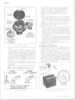
Fig. 38— Tool J-23339 Installed
Bleeding Tool (Fig. 38)
A special tool for bleeding the frame mounted booster
main cylinder is shown in Figure 38.
It will be necessary for the service man to install his
own bleeder adapter fitting to this tool. When bleeding
the system, always bleed the frame mounted boosters
before bleeding any wheel cylinders.
BENCH BLEEDING M A IN CYLINDERS
1. Install plugs in both outlet ports.
NOTE:
Plastic plugs that come with a replace
ment cylinder is recommended for this operation.
2. Clamp the main cylinder in a bench vise with the
front end tilted slightly down.
3. Fill both reservoirs with clean brake fluid.
4. Insert a rod with a smooth round end to the primary
piston and press in to compress the piston return
spring.
5. Release pressure on rod. Watch for air bubbles
in the reservoir fluid.
6. Repeat step 5 as long as bubbles appear.
7. Reposition main cylinder in vise so that the front
end is tilted slightly up.
8. Repeat steps 4-5-6.
9. Install diaphragm and cover on reservoir.
CAUTION:
Do not tighten vise too tight as da
mage to the main cylinder could result.
BRAKE PEDAL—-SERVICE BRAKE (Fig. 39)
NOTE:
All brake attachments are important at
taching parts in that they could affect the per
formance of vital components and systems,
and/or could result in major repair expense.
They must be replaced with parts of the same
part numbers or with equivalent parts if re
placement becomes necessary. Do not use re
placement parts of lesser quality or substitute
design. Torque values must be used as specified
during reassembly to assure proper retention
of these parts.
NOTE:
The brake pedal is an integral design
with the clutch pedal (except automatic trans
mission), necessitating the removal of the clutch
pedal before removing the brake pedal.
Removal
1. Remove the clutch pedal as outlined under "Clutch
Pedal" in Section 7.
2. Remove the pull back spring from the body bracket.
3. Remove the sleeve assembly screw attachment and
remove sleeve.
4. Disengage the push rod from the master cylinder and
drop the pedal to check for worn parts - inspect the
return spring, bracket attachment, and bushings for
needed repairs.
Installation
Reverse the above procedure and make certain the
brake pedal is secure and adjusted properly before operat
ing the vehicle.
Brake Pedal & Push Rod Travel Adjustment
A definite pedal push rod-to-main cylinder piston
clearance must be maintained on the dash mounted main
cylinder units. This clearance is adjusted as follows:
Threaded Rod Type Adjustment (Fig. 40)
1. After the brake pedal and pedal bumper have been
assembled, install the push rod and its attaching
parts. Tighten nut to 30 ft. lbs. torque. Then to
obtain the correct clearance between the push rod
and the master cylinder, adjust the push rod so that
the free pedal travel measured at the center of the
pedal pad is approximately 1/8 inch (fig. 41).
2. After tightening the locknut on the adjustable push
rod, recheck free travel.
NOTE:
All brake attachments are important at
taching parts in that the could affect the per
formance of vital components and systems, and/
10-30 CHEVROLET TRUCK SERVICE MANUAL
Содержание 10 1971 Series
Страница 1: ......
Страница 96: ......
Страница 100: ...10 30 CHEVROLET TRUCK SERVICE MANUAL Fig 4 10 30 Series Truck Frame FRAME 2 4 ...
Страница 120: ......
Страница 203: ...ENGINE 6 25 Fig 22L Engine Mounts 10 30 CHEVROLET TRUCK SERVICE MANUAL ...
Страница 215: ...ENGINE 6 37 REAR M O U NT Fig 21V Engine Mounts 10 30 CHEVROLET TRUCK SERVICE MANUAL ...
Страница 218: ......
Страница 249: ......
Страница 250: ...EMISSION CONTROL SYSTEMS 6T 4 Fig 3 Combination Emission Control System Routing V8 10 30 CHEVROLET TRUCK SERVICE MANUAL ...
Страница 324: ......
Страница 339: ...FUEL TANK AND EXHAUST SYSTEMS 8 15 SPECIAL TOOLS Fig 22 Special Tools 1 J 23346 Fuel Tank Gauge Remover and Installer ...
Страница 340: ......
Страница 365: ...10 30 CHEVROLET TRUCK SERVICE MANUAL Fig 43 Power Steering Pump M ounting STEERING 9 25 ...
Страница 368: ......
Страница 386: ......
Страница 390: ...ELECTRICAL BODY AND CHASSIS 12 4 10 30 CHEVROLET TRUCK SERVICE MANUAL ...
Страница 391: ......
Страница 392: ...ELECTRICAL BODY AND CHASSIS 12 6 Fig 5 Rear Lighting Composite 10 30 CHEVROLET TRUCK SERVICE MANUAL ...
Страница 409: ...ELECTRICAL BODY AND CHASSIS 12 23 Fig 27 Engine Compartment CA30 02 10 30 CHEVROLET TRUCK SERVICE MANUAL ...
Страница 410: ...ELECTRICAL BODY AND CHASSIS 12 24 18DK GRN 19 Fig 28 Instrument Panel CA30 02 10 30 CHEVROLET TRUCK SERVICE MANUAL ...
Страница 411: ...ELECTRICAL BODY AND CHASSIS 12 25 Fig 29 Instrument Panel CA30 02 10 30 CHEVROLET TRUCK SERVICE MANUAL ...
Страница 412: ...ELECTRICAL BODY AND CHASSIS 12 26 fh Ar r kk 4 Fig 30 Engine Compartment C A K A 10 20 CA30 03 z _ ...
Страница 416: ...ELECTRICAL BODY AND CHASSIS 12 30 Fig 34 Engine Compartment CA KA10 20 CA30 04 10 30 CHEVROLET TRUCK SERVICE MANUAL ...
Страница 420: ...ELECTRICAL BODY AND CHASSIS 12 34 Fig 38 Engine Compartment C A K A 1 0 20 06 16 10 30 CHEVROLET TRUCK SERVICE MANUAL ...
Страница 422: ...ELECTRICAL BODY AND CHASSIS 12 36 Fig 40 Instrument Panel C A K A 10 20 06 16 10 30 CHEVROLET TRUCK SERVICE MANUAL ...
Страница 423: ...ELECTRICAL BODY AND CHASSIS 12 37 Fig 41 R ear Lamps C A K A 1 0 20 06 16 10 30 CHEVROLET TRUCK SERVICE MANUAL ...
Страница 424: ...ELECTRICAL BODY AND CHASSIS 12 38 Fig 42 Engine Compartment CA KA10 20 CAl30 14 34 10 30 CHEVROLET TRUCK SERVICE MANUAL ...
Страница 426: ...ELECTRICAL BODY AND CHASSIS 12 40 Fig 44 Instrument Panel CA KA10 20 CA30 14 34 10 30 CHEVROLET TRUCK SERVICE MANUAL ...
Страница 428: ......
Страница 432: ......
Страница 449: ...SPECIFICATIONS 9 10 30 CHEVROLET TRUCK SERVICE MANUAL ...
Страница 463: ......
Страница 464: ......
Страница 465: ......
Страница 466: ......


