ENGINE 6-8
W INDOW
"H EX ” TYPE
WRENCH
SCREW
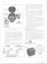
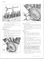
Fig. 15— Setting Point Dwell (Typical V8)
V8 ENGINES
• With engine running at idle, raise the adjustment
screw window and insert an Allen wrench in the
socket of the adjusting screw (fig. 15).
• Turn th^^fSs^ihg screw as required until a dwell
reading
pi
30° is jobtained. A 2° variation is allow
able forlwear> , / '
• Close acwrSs cover fully to prevent the entry of
dirt into the distributor.
NOTE:
If a dwell meter is not available, turn
adjusting screw clockwise until engine starts to
misfire, then turn screw one-half turn in the
opposite direction to complete adjustment.
IN LINE ENGINES
• Remove distributor cap and recheck point setting.
If dwell is still not within specifications check the
distributor as outlined in Section 6Y.
Check Dwell Variation
Slowly accelerate engine to 1500 rpm and note dwell
reading. Return engine to idle and note dwell reading.
If dwell variation exceeds specifications, check for worn
distributor shaft, worn distributor shaft bushing or loose
breaker plate.
Check and Adjust Ignition Timing (Fig. 16)
1. Disconnect the distributor spark advance hose and
plug the vacuum source opening.
2. Start engine and run at idle speed (See tune up chart
in Specification section.)
3. Aim timing light at timing tab.
NOTE:
The markings on the tabs are in 2“ incre
ments (the greatest number of markings on the
“ Before” side of the “O” ). The “O” marking
is TDC and all BTDC settings fall on the “ Be
fore” (advance) side of “O” .
4. Adjust the timing by loosening the distributor clamp
and rotating the distributor body as required, then
tighten the clamp and recheck timing.
5. Stop engine and remove timing light and reconnect
the spark advance hose.
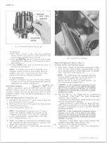
Fig. 16— Ignition Timing Marks
Adjust Idle Speed and Mixture (Fig. 17)
10 Series Vehicles with Gasoline Engines
1. With engine running at operating temperature, choke
valve in fully open position, parking brake on and
drive wheels blocked - adjust idle speed as follows
(See “ Tune-Up” Decal Figure 18):
NOTE:
All carburetors are equipped with idle
mixture limiter caps (fig. 17); the idle mixture is
preset and “ locked in” by these caps - no
attempt should be made to adjust mixture. Do
not remove mixture screw caps.
CAUTION:
If the Combination Emission Control
solenoid screw (fig. 17) is used to set engine
idle or if the solenoid is adjusted out of limits
as specified in Section 6M, a decrease in engine
braking may result.
• 250 and 292 Cu. In. (Single-Barrel Carburetor)
Disconnect “ Fuel Tank” line from Evaporation
Emission vapor canister.
Disconnect the distributor spark advance hose and
plug the vacuum source opening.
Adjust carburetor speed screw to obtain 550 rpm
with manual transmission in neutral; 500 rpm with
automatic transmission in drive. DO NOT ADJUST
SOLENOID SCREW.
CAUTION:
If the Combination Emission Control
solenoid screw (fig. 17) is used to set engine
idle or if the solenoid is adjusted out of limits
as specified in Section 6M, a decrease in engine
braking may result^
Reconnect “ Fuel Tank” line to vapor canister and
reconnect distributor spark advance hose.
«
307 Cu. In. (Two-Barrel Carburetor)
Disconnect “ Fuel Tank” line from Evaporation
Emission vapor canister.
10-30 CHEVROLET TRUCK SERVICE MANUAL
Содержание 10 1971 Series
Страница 1: ......
Страница 96: ......
Страница 100: ...10 30 CHEVROLET TRUCK SERVICE MANUAL Fig 4 10 30 Series Truck Frame FRAME 2 4 ...
Страница 120: ......
Страница 203: ...ENGINE 6 25 Fig 22L Engine Mounts 10 30 CHEVROLET TRUCK SERVICE MANUAL ...
Страница 215: ...ENGINE 6 37 REAR M O U NT Fig 21V Engine Mounts 10 30 CHEVROLET TRUCK SERVICE MANUAL ...
Страница 218: ......
Страница 249: ......
Страница 250: ...EMISSION CONTROL SYSTEMS 6T 4 Fig 3 Combination Emission Control System Routing V8 10 30 CHEVROLET TRUCK SERVICE MANUAL ...
Страница 324: ......
Страница 339: ...FUEL TANK AND EXHAUST SYSTEMS 8 15 SPECIAL TOOLS Fig 22 Special Tools 1 J 23346 Fuel Tank Gauge Remover and Installer ...
Страница 340: ......
Страница 365: ...10 30 CHEVROLET TRUCK SERVICE MANUAL Fig 43 Power Steering Pump M ounting STEERING 9 25 ...
Страница 368: ......
Страница 386: ......
Страница 390: ...ELECTRICAL BODY AND CHASSIS 12 4 10 30 CHEVROLET TRUCK SERVICE MANUAL ...
Страница 391: ......
Страница 392: ...ELECTRICAL BODY AND CHASSIS 12 6 Fig 5 Rear Lighting Composite 10 30 CHEVROLET TRUCK SERVICE MANUAL ...
Страница 409: ...ELECTRICAL BODY AND CHASSIS 12 23 Fig 27 Engine Compartment CA30 02 10 30 CHEVROLET TRUCK SERVICE MANUAL ...
Страница 410: ...ELECTRICAL BODY AND CHASSIS 12 24 18DK GRN 19 Fig 28 Instrument Panel CA30 02 10 30 CHEVROLET TRUCK SERVICE MANUAL ...
Страница 411: ...ELECTRICAL BODY AND CHASSIS 12 25 Fig 29 Instrument Panel CA30 02 10 30 CHEVROLET TRUCK SERVICE MANUAL ...
Страница 412: ...ELECTRICAL BODY AND CHASSIS 12 26 fh Ar r kk 4 Fig 30 Engine Compartment C A K A 10 20 CA30 03 z _ ...
Страница 416: ...ELECTRICAL BODY AND CHASSIS 12 30 Fig 34 Engine Compartment CA KA10 20 CA30 04 10 30 CHEVROLET TRUCK SERVICE MANUAL ...
Страница 420: ...ELECTRICAL BODY AND CHASSIS 12 34 Fig 38 Engine Compartment C A K A 1 0 20 06 16 10 30 CHEVROLET TRUCK SERVICE MANUAL ...
Страница 422: ...ELECTRICAL BODY AND CHASSIS 12 36 Fig 40 Instrument Panel C A K A 10 20 06 16 10 30 CHEVROLET TRUCK SERVICE MANUAL ...
Страница 423: ...ELECTRICAL BODY AND CHASSIS 12 37 Fig 41 R ear Lamps C A K A 1 0 20 06 16 10 30 CHEVROLET TRUCK SERVICE MANUAL ...
Страница 424: ...ELECTRICAL BODY AND CHASSIS 12 38 Fig 42 Engine Compartment CA KA10 20 CAl30 14 34 10 30 CHEVROLET TRUCK SERVICE MANUAL ...
Страница 426: ...ELECTRICAL BODY AND CHASSIS 12 40 Fig 44 Instrument Panel CA KA10 20 CA30 14 34 10 30 CHEVROLET TRUCK SERVICE MANUAL ...
Страница 428: ......
Страница 432: ......
Страница 449: ...SPECIFICATIONS 9 10 30 CHEVROLET TRUCK SERVICE MANUAL ...
Страница 463: ......
Страница 464: ......
Страница 465: ......
Страница 466: ......


