


CLUTCHES AND TRANSMISSIONS 7-33
1. Remove bottom pan attaching screws, pan, and
gasket.
2. Remove oil filter retainer bolt, oil filter, intake pipe
assembly and intake pipe to case “ O " ring. Discard
the oil filter and pipe to case "O ” ring.
3. Install new “ O” ring seal on intake pipe and place
pipe assembly into grommet on new filter assembly.
4. With
“ O”
ring on intake pipe, install pipe and
filter assembly into case, attaching filter to control
valve assembly with the retainer bolt.
5. Thoroughly clean bottom pan.
6. Affix new gasket to bottom pan with petroleum jelly.
7. Install bottom pan with attaching screws and torque
to specifications.
8. If only the pan has been removed, pour approximately
7-1/2 pints (U.S. measure, 6-1/4 pints Imperial
measure) of fluid into the transmission. If the
valve body has also been removed use 9-1/2 pints
(U.S. measure, 8 pints Imperial measure). After a
complete overhaul approximately 19 pints (U.S. mea
sure, 15-3/4 pints Imperial measure) are required.
Be sure container, spout, or funnel is clean.
9. Start engine and let idle (carburetor off fast idle
step). Place selector lever in P position and apply
hand brake.
10. With transmission warm (approximately 180°F.), add
fluid to bring level to full mark on indicator.
With transmission at room temperature (approx. 70°F.)
add fluid to bring level to 1/4 inch below add mark.
CAUTION:
Do not overfill. Foaming will result.
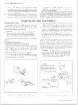
PRESSURE REGULATOR VALVE
NOTE:
The 1971 solid type pressure regulator
valve does not contain oil holes and an orifice
cup plug like the previous pressure regulator
valve. The solid style valve must only be used in
the pump cover with the squared off pressure
regulator boss. (Pressure boost bushing end).
See Fig. 5T. The previous pressure regulator
valve with the oil holes and orifice cup plug will
be used to service either type pump cover.
Removal
1. Remove bottom pan and filter.
2o Compress regulator boost valve bushing against
pressure regulator spring and remove snap ring,
using J-5403 pliers.
30 Remove regulator boost valve bushing and valve.
4. Remove pressure regulator spring.
5. Remove regulator valve, spring r e t a i n e r , and
spacer(s) if present.
Installation
Installation of the pressure regulator valve is the re
verse of the removal.
Adjust oil level.
CONTROL VALVE BODY
Removal
1. Remove bottom pan and filter.
2. Disconnect lead wire from pressure switch assembly.
3. Remove control valve body attaching screws and de
tent roller spring assembly.
NOTE:
Do not remove solenoid attaching
screws.
CAUTION:
If the transmission is in the ve
hicle, the front servo parts may drop out as
the control valve assembly is removed.
4. Remove control valve body assembly and governor
pipes. If care is taken in removing control valve
body the six (6) check balls will stay in place above
the spacer plate.
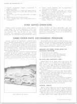
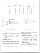
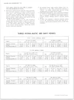
5. Remove the governor screen assembly from end of
governor feed pipe or from the governor feed pipe
hole in the case (fig. 6T). Clean governor screen in
clean solvent and air dry.
CAUTION:
Do not drop manual valve.
6. Remove the governor pipes and manual valve from
control valve body.
Installation
For Installation see Overhaul Manual.
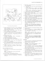
FOR IDENTIFICATION-
SQUARED OFF PRESSURE
REG. BOSS.
PUMP COVER
G O VERNO R SCREEN
ASSY.
GO VERNO R FEED
PIPE HOLE
Fig. 5T — Pressure Regulator V a lv e
Fig. 6T— G ove rn or Screen Position
10-30 CHEVROLET TRUCK SERVICE MANUAL
Содержание 10 1971 Series
Страница 1: ......
Страница 96: ......
Страница 100: ...10 30 CHEVROLET TRUCK SERVICE MANUAL Fig 4 10 30 Series Truck Frame FRAME 2 4 ...
Страница 120: ......
Страница 203: ...ENGINE 6 25 Fig 22L Engine Mounts 10 30 CHEVROLET TRUCK SERVICE MANUAL ...
Страница 215: ...ENGINE 6 37 REAR M O U NT Fig 21V Engine Mounts 10 30 CHEVROLET TRUCK SERVICE MANUAL ...
Страница 218: ......
Страница 249: ......
Страница 250: ...EMISSION CONTROL SYSTEMS 6T 4 Fig 3 Combination Emission Control System Routing V8 10 30 CHEVROLET TRUCK SERVICE MANUAL ...
Страница 324: ......
Страница 339: ...FUEL TANK AND EXHAUST SYSTEMS 8 15 SPECIAL TOOLS Fig 22 Special Tools 1 J 23346 Fuel Tank Gauge Remover and Installer ...
Страница 340: ......
Страница 365: ...10 30 CHEVROLET TRUCK SERVICE MANUAL Fig 43 Power Steering Pump M ounting STEERING 9 25 ...
Страница 368: ......
Страница 386: ......
Страница 390: ...ELECTRICAL BODY AND CHASSIS 12 4 10 30 CHEVROLET TRUCK SERVICE MANUAL ...
Страница 391: ......
Страница 392: ...ELECTRICAL BODY AND CHASSIS 12 6 Fig 5 Rear Lighting Composite 10 30 CHEVROLET TRUCK SERVICE MANUAL ...
Страница 409: ...ELECTRICAL BODY AND CHASSIS 12 23 Fig 27 Engine Compartment CA30 02 10 30 CHEVROLET TRUCK SERVICE MANUAL ...
Страница 410: ...ELECTRICAL BODY AND CHASSIS 12 24 18DK GRN 19 Fig 28 Instrument Panel CA30 02 10 30 CHEVROLET TRUCK SERVICE MANUAL ...
Страница 411: ...ELECTRICAL BODY AND CHASSIS 12 25 Fig 29 Instrument Panel CA30 02 10 30 CHEVROLET TRUCK SERVICE MANUAL ...
Страница 412: ...ELECTRICAL BODY AND CHASSIS 12 26 fh Ar r kk 4 Fig 30 Engine Compartment C A K A 10 20 CA30 03 z _ ...
Страница 416: ...ELECTRICAL BODY AND CHASSIS 12 30 Fig 34 Engine Compartment CA KA10 20 CA30 04 10 30 CHEVROLET TRUCK SERVICE MANUAL ...
Страница 420: ...ELECTRICAL BODY AND CHASSIS 12 34 Fig 38 Engine Compartment C A K A 1 0 20 06 16 10 30 CHEVROLET TRUCK SERVICE MANUAL ...
Страница 422: ...ELECTRICAL BODY AND CHASSIS 12 36 Fig 40 Instrument Panel C A K A 10 20 06 16 10 30 CHEVROLET TRUCK SERVICE MANUAL ...
Страница 423: ...ELECTRICAL BODY AND CHASSIS 12 37 Fig 41 R ear Lamps C A K A 1 0 20 06 16 10 30 CHEVROLET TRUCK SERVICE MANUAL ...
Страница 424: ...ELECTRICAL BODY AND CHASSIS 12 38 Fig 42 Engine Compartment CA KA10 20 CAl30 14 34 10 30 CHEVROLET TRUCK SERVICE MANUAL ...
Страница 426: ...ELECTRICAL BODY AND CHASSIS 12 40 Fig 44 Instrument Panel CA KA10 20 CA30 14 34 10 30 CHEVROLET TRUCK SERVICE MANUAL ...
Страница 428: ......
Страница 432: ......
Страница 449: ...SPECIFICATIONS 9 10 30 CHEVROLET TRUCK SERVICE MANUAL ...
Страница 463: ......
Страница 464: ......
Страница 465: ......
Страница 466: ......