
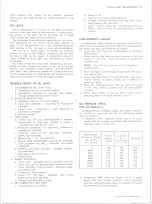


CLUTCHES AND TRANSMISSIONS 7-34
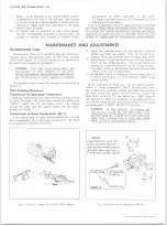
G O V ERN O R
NOTE:
If difficulty is encountered when remov
ing the governor assembly, it may be necessary
to remove the oil pan and withdraw governor
pipes (approximately 1/8") to free governor
assembly.
Removal
1. Remove governor cover attaching screws, cover,
and gasket.
2. Discard gasket.
3. Withdraw governor assembly from case.
Installation
Installation of the governor assembly is the reverse of
the removal. Use a new gasket under the governor cover.
Adjust oil level.
MODULATOR A N D M ODULATOR VALVE
Removal
1. Remove modulator assembly attaching screw and
retainer.
2. Remove modulator assembly from case. Discard
“ O”
ring seal.
3. Remove modulator valve from case.
Installation
Installation of the modulator assembly and modulator
valve is the reverse of the removal. Use a new “ O” ring
seal on the modulator assembly.
Adjust oil level.
PARKING LIN K A G E-10, 20 SERIES
Removal
1. Remove bottom pan and oil filter.
2. Unthread jam nut holding detent lever to manual
shaft.
3. Remove manual shaft retaining pin from case.
4. Remove manual shaft and jam nut from case.
NOTE:
Do not remove manual shaft seal unless
replacement is required.
5. Remove parking actuator rod and detent l e v e r
assembly.
6. Remove parking pawl bracket attaching screws and
bracket.
7. Remove parking pawl return spring.
NOTE:
The following steps should not be com
pleted unless part replacement is required.
8. Remove parking pawl shaft retainer.
9. Remove parking pawl shaft, cup plug parking pawl
shaft, and parking pawl.
Installation
Installation of the parking linkage is the reverse of the
removal. Use new seal and cup plug, if removed, and new
bottom pan gasket.
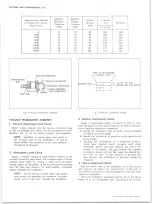
REAR SEAL
Removal
1. Remove propeller shaft.
2. Pry seal out with screw driver.
Installation
A ll M odels Except C M
1. a. Use a non-hardening sealer on outside of seal
body; and using ToolJ-21359, drive seal in place.
M o d e l C M
b. Use a non-hardening sealer on outside of seal
body; and using Tool J-21464, drive seal in place.
2. Re-install propeller shaft.
OTHER SERVICE WITH TRAN SM ISSIO N IN VEHICLE
The following operations when done as single opera
tions and not as part of a general overhaul should, as a
practical matter, be performed with the transmission in
the vehicle. Refer to the “ Transmission Disassembly
and Reassembly” section of the Overhaul Manual for
service procedures.
a. Oil filler pipe and “ O” ring seal.
b. Oil pan and gasket.
c. Down shift solenoid or connector.
TRAN SM ISSIO N
Before raising the truck, disconnect the battery and re
lease the parking brake.
1. Raise truck on hoist.
2. Remove propeller shaft.
3. Disconnect speedometer cable, electrical lead to
case connector, vacuum line at modulator, and oil
cooler pipes.
4. Disconnect shift control linkage.
5. Support transmission with suitable transmission
jack.
6. Disconnect rear mount from frame crossmember.
d. Valve body spacer plate, gasket and check balls.
e. Front accumulator piston.
f . Rear servo and rear accumulator assembly.
g. Rear band apply checking with Tool J-21370.
h. Front servo assembly.
i . Speedo driven gear.
j. Case extension or gasket.
k. Filter and
“ O”
ring.
1. Pressure switch assembly.
REPLACEMENT
7. Remove two bolts at each end of frame crossmember
and remove crossmember.
8. Remove converter under pan.
9. Remove converter to flywheel bolts.
10. Loosen exhaust pipe to manifold bolts approximately
1/4 inch, and lower transmission until jack is barely
supporting it.
11. Remove transmission to engine mounting bolts and
remove oil filler tube at transmission.
12. Raise transmission to its normal position, support
engine with jack and slide transmission rearward
10-30 CHEVROLET TRUCK SERVICE MANUAL
Содержание 10 1971 Series
Страница 1: ......
Страница 96: ......
Страница 100: ...10 30 CHEVROLET TRUCK SERVICE MANUAL Fig 4 10 30 Series Truck Frame FRAME 2 4 ...
Страница 120: ......
Страница 203: ...ENGINE 6 25 Fig 22L Engine Mounts 10 30 CHEVROLET TRUCK SERVICE MANUAL ...
Страница 215: ...ENGINE 6 37 REAR M O U NT Fig 21V Engine Mounts 10 30 CHEVROLET TRUCK SERVICE MANUAL ...
Страница 218: ......
Страница 249: ......
Страница 250: ...EMISSION CONTROL SYSTEMS 6T 4 Fig 3 Combination Emission Control System Routing V8 10 30 CHEVROLET TRUCK SERVICE MANUAL ...
Страница 324: ......
Страница 339: ...FUEL TANK AND EXHAUST SYSTEMS 8 15 SPECIAL TOOLS Fig 22 Special Tools 1 J 23346 Fuel Tank Gauge Remover and Installer ...
Страница 340: ......
Страница 365: ...10 30 CHEVROLET TRUCK SERVICE MANUAL Fig 43 Power Steering Pump M ounting STEERING 9 25 ...
Страница 368: ......
Страница 386: ......
Страница 390: ...ELECTRICAL BODY AND CHASSIS 12 4 10 30 CHEVROLET TRUCK SERVICE MANUAL ...
Страница 391: ......
Страница 392: ...ELECTRICAL BODY AND CHASSIS 12 6 Fig 5 Rear Lighting Composite 10 30 CHEVROLET TRUCK SERVICE MANUAL ...
Страница 409: ...ELECTRICAL BODY AND CHASSIS 12 23 Fig 27 Engine Compartment CA30 02 10 30 CHEVROLET TRUCK SERVICE MANUAL ...
Страница 410: ...ELECTRICAL BODY AND CHASSIS 12 24 18DK GRN 19 Fig 28 Instrument Panel CA30 02 10 30 CHEVROLET TRUCK SERVICE MANUAL ...
Страница 411: ...ELECTRICAL BODY AND CHASSIS 12 25 Fig 29 Instrument Panel CA30 02 10 30 CHEVROLET TRUCK SERVICE MANUAL ...
Страница 412: ...ELECTRICAL BODY AND CHASSIS 12 26 fh Ar r kk 4 Fig 30 Engine Compartment C A K A 10 20 CA30 03 z _ ...
Страница 416: ...ELECTRICAL BODY AND CHASSIS 12 30 Fig 34 Engine Compartment CA KA10 20 CA30 04 10 30 CHEVROLET TRUCK SERVICE MANUAL ...
Страница 420: ...ELECTRICAL BODY AND CHASSIS 12 34 Fig 38 Engine Compartment C A K A 1 0 20 06 16 10 30 CHEVROLET TRUCK SERVICE MANUAL ...
Страница 422: ...ELECTRICAL BODY AND CHASSIS 12 36 Fig 40 Instrument Panel C A K A 10 20 06 16 10 30 CHEVROLET TRUCK SERVICE MANUAL ...
Страница 423: ...ELECTRICAL BODY AND CHASSIS 12 37 Fig 41 R ear Lamps C A K A 1 0 20 06 16 10 30 CHEVROLET TRUCK SERVICE MANUAL ...
Страница 424: ...ELECTRICAL BODY AND CHASSIS 12 38 Fig 42 Engine Compartment CA KA10 20 CAl30 14 34 10 30 CHEVROLET TRUCK SERVICE MANUAL ...
Страница 426: ...ELECTRICAL BODY AND CHASSIS 12 40 Fig 44 Instrument Panel CA KA10 20 CA30 14 34 10 30 CHEVROLET TRUCK SERVICE MANUAL ...
Страница 428: ......
Страница 432: ......
Страница 449: ...SPECIFICATIONS 9 10 30 CHEVROLET TRUCK SERVICE MANUAL ...
Страница 463: ......
Страница 464: ......
Страница 465: ......
Страница 466: ......


