U600 User’s Guide
Parameters
Version 1.4
Aerotech, Inc.
C-67
The absolute value of this parameter (in milliseconds) determines the minimum time that
a CNC program block may execute in. Attempting to exceed this limit will cause the
velocity of the CNC block to be scaled down.
The sign, if negative, will force the velocity of G2 / G3 (G12 / G13) commands to slow
down only enough, such that the CNC Profiler is able to calculate 3 points during the arc.
This guarantees that the arc will not be a linear segment, created from 2 points (starting
and ending point).
C.4.13.
ChordicalToleranceInch
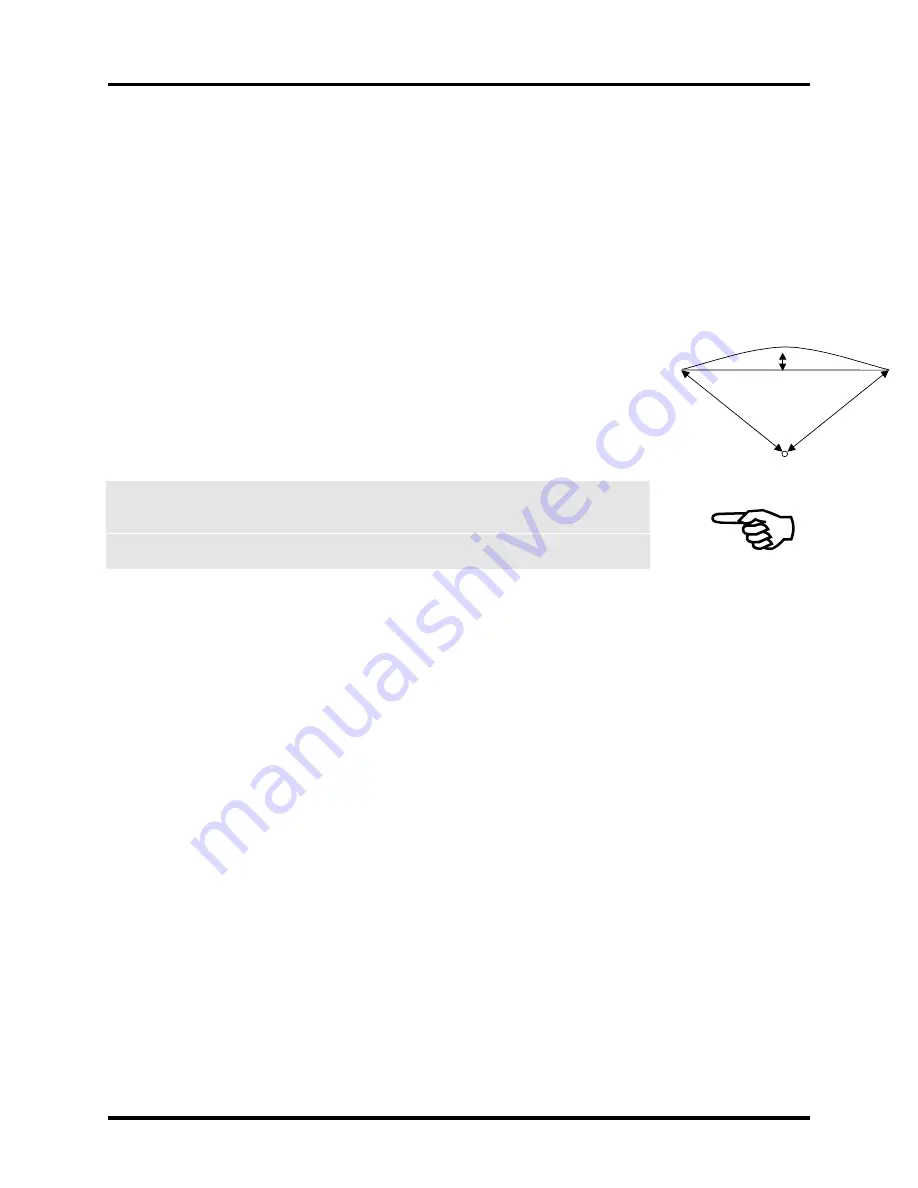
This task parameter will disable warning messages for arc’s (G2/G3/G12/G13) that
execute in less than the time specified by UpdateTimeSec (creating a splined arc with
only 2 points), whose chord distance is less than the value of this parameter. The chord
distance is defined as the maximum distance from the center of a line (drawn from the
starting point to the ending point of the arc) to the circumference of the arc. In the
illustration below, the programmed arc will not be generated, but, the linear move
segment will be generated from the start point to the end point.
When a line is generated instead of an arc, acceleration limiting will not occur for the
angle of the line, it will compensate only for the programmed arc. If the line
generated, is non-tangential to the previous move, over-shoot will occur.
An error (not just a warning) may be generated on this condition by setting the
ThrowWarningsAsTaskFaults task parameter to one.
C.4.14.
CommandVelocityVariance
This task parameter will, in certain situations (during deceleration within a series of short
contoured moves) due to the limitations of integer times (in milliseconds) the CNC
Profiler will produce smoother contours, if it could produce non-linear behavior of
velocity vs. time during one particular time slice. Increasing the value of this parameter
will reduce the frequency of extra long or extra short slices, which may improve the
smoothness of high speed machining profiles.
C.4.15.
Coord1Plane
This task parameter specifies which plane is active in coordinate system 1. Coordinate
system 1 is used for the circular G-codes G2 and G3. Plane 1 consists of the axis
specified by Coord1I and Coord1J task parameters. Plane 2 is defined by Coord1J and
Coord1K task parameters. Plane 3 is defined by Coord1K and Coord1I task parameters.
Any circular motion performed in coordinate system 1 must be in the active plane. The
active plane determines the default axes for incomplete targets of circular moves, refer to
the figure below. This parameter is 1 based, where 1 represents plane 1, comprised of the
axes defined by the Coord1I and Coord1J task parameters, as shown in Figure C-12.
Refer to Figure C-13 also.
Radius
Chord
Содержание UNIDEX 600 Series
Страница 19: ...Table of Contents U600 User s Guide xviii Aerotech Inc Version 1 4...
Страница 27: ...Preface U600 User s Guide xxvi Aerotech Inc Version 1 4...
Страница 163: ...AerPlot U600 User s Guide 6 6 Aerotech Inc Version 1 4...
Страница 169: ...AerReg U600 User s Guide 8 4 Aerotech Inc Version 1 4...
Страница 177: ...AerPlotIO U600 User s Guide 10 4 Aerotech Inc Version 1 4...
Страница 179: ...Filter U600 User s Guide 11 2 Aerotech Inc Version 1 4...
Страница 219: ...PrmSetup U600 User s Guide 13 2 Aerotech Inc Version 1 4...
Страница 223: ...Glossary of Terms U600 User s Guide A 4 Aerotech Inc Version 1 4...
Страница 353: ......


