background image

Other Features 

Page 160 


Frog 2 Operating Manual – Issue 4.3 


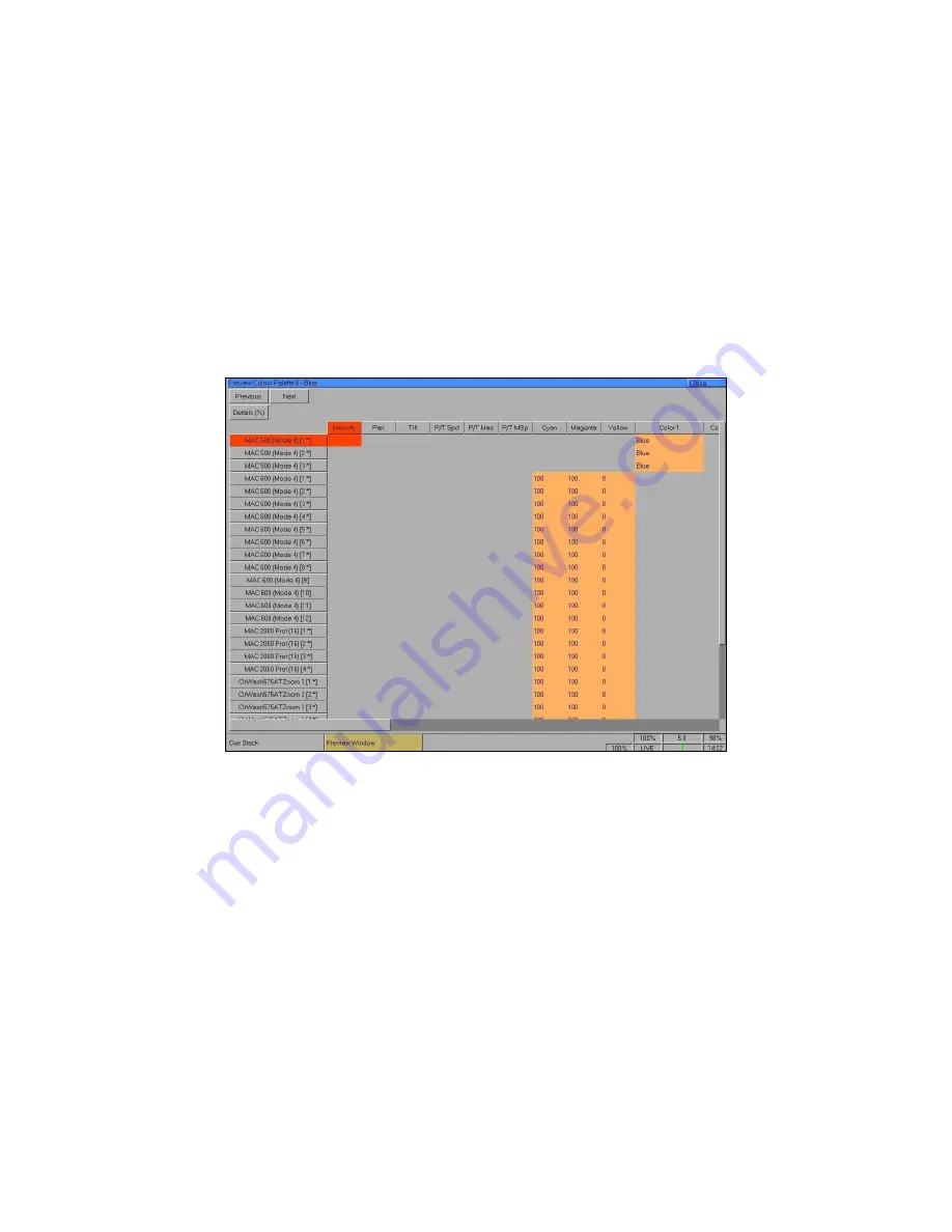
Preview Palette Windows 

The contents of a palette can be seen by displaying the 

Preview Colour Palette Window, 

Preview  Beamshape  Palette,  Preview  Position  Palette 

or

  Preview  Effects  Palette 

on 

the monitor by entering the following command: 

VIEW <attribute> N ENTER


 (<attribute> = COLOUR, BEAM, POSITION or  EFFECTS) 

The  Preview  Palette  Windows  are  the  same  format  as  the  Program  Window  and  show 
what output levels are programmed in the specified palette on a fixture by fixture basis.  

The [Previous] and [Next] buttons can be used to view the palettes in sequence.  


Summary of Contents for FROG 2

Page 1: ...FROG 2 OPERATING MANUAL...

Page 2: ......

Page 3: ...y with the limits for a Class A digital device pursuant to part 15 of the FCC rules These limits are designed to provide reasonable protection against harmful interference when the equipment is operat...

Page 4: ...Absolute Addressing 56 Desk Setup 57 Files 66 Clear Options 70 Network 71 Groups 77 Group Window 77 Master Groups 78 Automatic Groups 78 User Defined Groups 78 Naming Groups 79 Copying Groups 79 Movi...

Page 5: ...Ks 135 The UDF UDK Window 135 The UDK Setup Window 136 Group UDK 138 Fixture UDK 138 Palette UDK 138 Cue UDK 139 Channel Data UDK 139 Macro UDK 139 Editing User Definable Keys 140 Deleting User Defina...

Page 6: ...162 Output Window 163 DMX Output Window 165 Active Playback Window 165 User Views 166 Artnet 168 Software Updates 168 Glossary 169 Technical Specification 173 Power Supply 173 Audio 173 Remote Input...

Page 7: ...ch function this manual is divided into chapters one for each major area of control As the Frog 2 is a complex lighting desk which can be set up in many different ways the best tool in learning the de...

Page 8: ...ne which is displayed on the touch screen Commands can be entered using the front panel keys touch screen control wheels external keyboard or by clicking on objects with a mouse Control Channels The d...

Page 9: ...Override or Virtual Playback Master Fader functions User Definable Keys UDK The desk provides 100 pages of 20 User Definable Keys The User Definable Keys may be assigned to Groups Fixtures Palettes E...

Page 10: ...nd displays on the front panel of the Frog 2 desk The front panel controls have been divided into the following sections User Definable Faders UDF Grand Master and Blackout Manual Playbacks Function K...

Page 11: ...eration of each individual flash button can be set to flash or latch as required Grand Master and Blackout The GRAND MASTER fader controls the final output values of all fixture intensity channels res...

Page 12: ...ere are 10 sets of manual playback controls each of which consists of a MASTER fader SELECT FLASH PAUSE and GO keys The RELEASE key is used to release channels being controlled by the currently select...

Page 13: ...channel levels DMX addresses etc The backspace key removes the last instruction entered on the command line The slash key is used for separating stack and cue numbers eg 3 5 stack 3 cue 5 or fade up...

Page 14: ...his section The PAGE UP and PAGE DOWN buttons are used to select the required page Pressing the PAGE UP and PAGE DOWN buttons together selects page 1 Each User Definable Key contains a red LED The ope...

Page 15: ...es the Virtual Playback Master Level Grand Master level Live Blind Macro indicator Memory Meter and Time Value Below the Status Line is the Command Line which shows the command syntax as it is entered...

Page 16: ...is selected The cursor keys up down left and right are used to move around fields on the touch screen or active monitor screen These keys are equivalent to the four cursor keys on the external keyboar...

Page 17: ...rnal power supply has a separate switch on it so if you see no immediate response check you have both power switches set to ON and that the IEC lead is firmly attached to the external power supply Whe...

Page 18: ...keys to select the required manufacturer eg MARTIN Press the right arrow key to move the cursor to the fixtures into the right hand column Scroll down or use the cursor keys to select the required fi...

Page 19: ...The Frog 2 has four universes of DMX output numbered 1 to 4 It is important to ensure you patch the fixtures to the correct DMX universe The patch window can display the patch in three different view...

Page 20: ...e DMX start address and press ENTER For example GROUP MAC 500 1 274 ENTER Patching by Fixture Number If you have assigned each fixture an individual fixture number in the Edit Fixtures screen you can...

Page 21: ...displayed on the touch screen and the monitor To make changes to a particular fixture or a complete group of fixtures first select the fixture group The name of the group is displayed in the header of...

Page 22: ...ber for the first fixture in the group and press ENTER For example select the MAC 500 fixture group and enter 501 in the All row and No column The MAC 500 fixtures will be renumbered 501 502 503 etc E...

Page 23: ...adjust desk lamp brightness Peripheral Allow mouse or trackball to control pan and tilt parameters display soft keyboard on the touch screen wheel sensitivity Inputs Set up SMPTE and MIDI Timecode CA...

Page 24: ...ice eg memory stick included with your Frog 2 or to recordable CD Press the Files key on the touch screen or monitor Press the Save Show key to enter the Save Show screen Press the Destination Device...

Page 25: ...lect the show file you wish to load using the cursor keys Ensure that you have the correct Load Option selected default Load Complete Show Press OK key to load the show The desk will load the show int...

Page 26: ...r press the Program Window key on the touch screen As you select fixtures and adjust their parameters with the control wheels the corresponding information is shown in the Program Window The fixture p...

Page 27: ...n Homing the Fixtures The easiest way to see which fixtures in the rig you are controlling is to home them This will set their position Pan and Tilt to 50 the dimmer to 100 with an open white beam no...

Page 28: ...2 3 FULL ENTER sets the intensity output of fixtures 2 and 3 to 100 5 THRU 10 N ENTER sets the intensity output of fixtures 5 to 10 to N 5 THRU 10 FULL ENTER sets the intensity output of fixtures 5 to...

Page 29: ...e below COLOUR has been selected and the fixture parameters Cyan Magenta and Yellow are assigned to the three control wheels If the fixture has more than three controllable parameters for the selected...

Page 30: ...ameter is indicated on the touch screen and in the Program Window by it s background colour grey indicates that the parameter is untagged green indicates that the parameter is tagged If a parameter s...

Page 31: ...imply enter the following command RECORD ENTER If you wish to record the fixture data to a particular cue rather than the next available cue then enter the following command RECORD N ENTER N Cue Numbe...

Page 32: ...lues soft button and then select Fade or Delay from the drop down menu as required Program Window Fade View In the Fade view the current fade times for each fixture parameter are displayed in table fo...

Page 33: ...unrecorded commands and sends fixtures to their default values with the exception of the intensity which is kept at 0 To play back the cues in a cue stack in sequence first select the required page o...

Page 34: ...tte could include beamshape and position etc Palette Windows Each set of palettes has it s own palette window To display a palette window on the monitor hold down the SHIFT key and then press the appr...

Page 35: ...name to a palette enter either of the following commands COLOUR N SET or SET COLOUR N ENTER Type in the name using the external keyboard and then press the ENTER key to confirm Outputting Palettes To...

Page 36: ...the UDF Setup Window on the touch screen hold down the SETUP key and then press one of the User Definable Fader flash buttons This window allows the user to set the various parameters for the individ...

Page 37: ...ow To display the UDK Setup Window on the touch screen hold down the SETUP key and then press one of the User Definable Keys This window allows the user to set the various parameters of the individual...

Page 38: ...er Groups are displayed in a toolbar on the touch screen whenever you select the GROUP key Master Groups are not referenced by Group Number and do not appear in the Group Window Automatic Groups In Se...

Page 39: ...lear Options Network On entering Setup the Patch option is selected automatically and the corresponding soft buttons are displayed on the touch screen and monitor The Setup Window on the monitor shows...

Page 40: ...ress the Add Fixtures key on the touch screen The Fixture Schedule Window is displayed on the touch screen The left hand column in this window allows you to select the fixture manufacturer Scroll down...

Page 41: ...d added to the fixture library on the desk Selecting a user fixture type and specifying the number of that type in the fixture schedule is carried out in the same way as for any of the normal fixture...

Page 42: ...tures and Channels The default view is the Outputs view see below Patching a Group of Fixtures To patch an entire group of fixtures eg All MAC 250s sequentially from a start address Press the GROUP ke...

Page 43: ...e Fixture Part button on the touch screen is used when patching the non intensity part of the composite fixture for example Press GROUP and then select the VL5 button on the toolbar Type in the comman...

Page 44: ...in the Patch Window Press the Patch View key in the Patch Window and then select Outputs Fixtures or Channels from the drop down menu The different patch views are described in the sections below Out...

Page 45: ...e listed in group order Alignment data is only displayed if it has been changed from the defaults Patch addresses are displayed in the format universe address in normal addressing mode or simply the a...

Page 46: ...st select the fixture group by pressing the GROUP button until the required group is displayed in the touch screen All the fixtures in this group are now displayed in the Edit Fixtures window Press th...

Page 47: ...r to the ALL row and No column and then press the SET key Enter the fixture number for the first fixture in the group and press ENTER Example Select the MAC 500 fixture group and enter 501 in the ALL...

Page 48: ...utput when the fixture is homed or highlighted The Home values for fixture parameters are taken from the fixture profile data stored in the fixture library in the desk They are initially set to values...

Page 49: ...gle between the values Yes and No Select the required value and then press the ENTER key Now any adjustments you make to the parameter you changed will be inverted in the DMX outputs making all your f...

Page 50: ...yet been patched to the DMX output then the corresponding DMX column will show Add In the example above Fixture numbers 101 to 105 are patched to DMX universe 2 address 1 13 25 37 and 49 respectively...

Page 51: ...ress in the Address field provided or press the Next Address button to automatically pick up the next available patch address in the selected universe Press the OK button to complete the patching oper...

Page 52: ...DMX address in the Address field provided or press the Next Address button to automatically pick up the next available patch address in the selected universe Press the OK button to complete the patch...

Page 53: ...and a Fixture Part button that selects which part of the fixture is displayed on the screen eg All Parts Lamp Scroll DMX In Field The DMX In field in the patch table shows the DMX In address assigned...

Page 54: ...masters and palettes as far as possible Parameters in the new fixture type that were not present in the original fixture type are left unprogrammed Select the fixture s to be changed Go to the Type co...

Page 55: ...f standard effects palettes as described below Colour Palettes The desk provides the following standard colour palettes White Red Orange Yellow Green Blue Violet Cyan Magenta and Pink Fixtures with co...

Page 56: ...me Position palette which sets the Pan and Tilt parameters to a value of 50 Effects Palettes The desk generates a number of standard effects see Effects chapter for details Absolute Addressing Pressin...

Page 57: ...E and MIDI Timecode CAN Set Time Set Date Assign Remote Switches Outputs Configure DMX universes to DMX output sockets Behaviour Keep parameters separate options Page Holdover if Active Confirm Overwr...

Page 58: ...tor screen s will be turned off To restore the touch screen back light and monitor screen s press the touch screen or any key on the front panel of the desk Touch Screen Brightness Range 0 100 Default...

Page 59: ...s this will only take effect when fixtures are selected and the Position attribute is selected In this situation the mouse pointer is removed temporarily from the corresponding monitor screen In all o...

Page 60: ...the touch screen The Set Time Window is displayed on the touch screen Enter the correct time in the field provided and then confirm by selecting the OK button Set Date Press the Set Date key on the to...

Page 61: ...ut 1 Disabled DMX Universe 1 DMX Universe 2 DMX Universe 3 DMX Universe 4 Default DMX Universe 1 DMX Output 2 Disabled DMX Universe 1 DMX Universe 2 DMX Universe 3 DMX Universe 4 Default DMX Universe...

Page 62: ...arameters in that attribute will be tagged automatically eg in a CMY fixture if Cyan is adjusted then Cyan Magenta Yellow and any other colour parameter for the fixture will be tagged automatically Pa...

Page 63: ...59 9 Default 0 Intensity Delay Down Range 0 99 59 9 Default 0 Intensity Fade Up Range 0 99 59 9 Default 3 seconds Intensity Fade Down Range 0 99 59 9 Default 3 seconds Colour Delay Range 0 99 59 9 Def...

Page 64: ...anual Fader 1 Way Manual Fader 2 Way default HTP Master Chase Options Chase Drive Range Auto Bass Manual Beat default Auto Chase Direction Range Forward Backward Bounce Random Chase Speed Range 0 200...

Page 65: ...n allows the user to change the lock code PIN for the desk The lock code PIN is a four digit number 0000 9999 The lock code can be entered via the numeric keypad on the front panel or external keyboar...

Page 66: ...the drive Press the Files key on the touch screen Press the Save Show key on the touch screen The Save Show window is displayed on the touch screen Select the desired storage device by pressing the De...

Page 67: ...ce by pressing on the Source Device toggle box This will cycle through all the available devices so select the one you require Select the required show from the list of available shows displayed Selec...

Page 68: ...o the fixture library on the desk Selecting a user fixture type and setting the number of that type in the fixture schedule is performed in the same way as for any of the normal fixture types already...

Page 69: ...ess Press SETUP then press the Files key on the touch screen Press the Update Desk Software key on the touch screen You will be presented with a list of the upd files found on the USB memory stick Sel...

Page 70: ...ptions and Reset Desk Select the required option A confirmation window is displayed on the touch screen Select the Yes button to confirm the clear option A summary of the Clear Options is given below...

Page 71: ...cables can be used Devices receiving ArtNet must be located in the same subnet and IP range as the transmitting console For Capture it is suggested you set the computer IP address to 2 0 0 Once the c...

Page 72: ...Artnet for bidirectional communications Using this method it is possible to move your fixtures on Light Converse and see the effects on the desk or highlight the fixtures on the visualisation when the...

Page 73: ...the Zero 88 website Select the required option eg Transmit Zero Wire The MFKs change to display the corresponding options or a numeric keypad Use the MFKs to select the option or enter a numeric value...

Page 74: ...e The Capture visualiser has now been integrated with the Leap Frog 48 96 desk software Select the Capture option The MFKs and monitor will then display the Capture options which are summarised in the...

Page 75: ...then display the WYSIWYG options which are summarised in the following table Option Range Default Notes Enable WYSIWYG Yes or No No Use DHCP Address Yes or No Yes IP Address The IP address to use if U...

Page 76: ...Setup Page 76 Frog 2 Operating Manual Issue 4 3...

Page 77: ...c Groups can also be assigned to User Definable Faders UDF and User Definable Keys UDK Group Window To display the Group Window on the monitor hold down the SHIFT key and then press the GROUP key The...

Page 78: ...option to generate a set of automatic groups based on the fixture types in the schedule The desk generates a group for each of the Master Groups plus odd and even groups for each different fixture typ...

Page 79: ...N ENTER Type in the name of the group using the external keyboard and then press ENTER Copying Groups To copy a group enter the following command GROUP N COPY P ENTER Copies Group N to Group P Moving...

Page 80: ...Groups Page 80 Frog 2 Operating Manual Issue 4 3...

Page 81: ...effect UDF or UDK The Program Window The Program Window is central to the programming functionality on the Frog 2 desk It is recommended but not mandatory that the Program Window is displayed on one...

Page 82: ...eter values will be displayed as the parameter detail names eg Red Gobo 1 where they are defined in the fixture data If parameter details are not defined the window will show the actual numerical valu...

Page 83: ...oup type in their fixture numbers followed by ENTER for example 1 ENTER selects fixture 1 2 3 ENTER selects fixtures 2 and 3 5 THRU 10 ENTER selects fixtures 5 6 7 8 9 and 10 Alternatively you can use...

Page 84: ...xture 1 to N 1 FULL ENTER sets the intensity output of fixture 1 to 100 2 3 N ENTER sets the intensity output of fixtures 2 and 3 to N 2 3 FULL ENTER sets the intensity output of fixtures 2 and 3 to 1...

Page 85: ...ol wheels First select the required fixture s and then press the BEAM key The beamshape parameters for the fixture are assigned to the control wheels and are indicated on the lower part of the touch s...

Page 86: ...2 THRU 10 ENTER Copies all fixture parameter values from fixture 1 to fixtures 2 to 10 1 COPY GROUP N ENTER Copies all fixture parameter values from fixture 1 to the fixtures in group N Tagging Parame...

Page 87: ...mply with Smart Tags enabled you no longer have to think about Tracking The desk will insert whatever tracking is required to make your show work including ignoring fixtures whose intensity is set to...

Page 88: ...mine what data will be recorded Snapshot When Snapshot is selected the Snapshot button turns green and the remaining buttons on the top row are greyed out and no longer accessible All the attribute se...

Page 89: ...exclusive with the default option being Track Forward as shown above An example of each tracking option is given below CUE 1 CUE 2 CUE 3 CUE 4 CUE 5 CUE 6 CUE 7 CUE 8 CUE 9 CUE 10 Green Blue Green Gre...

Page 90: ...from existing cues palettes UDFs or UDKs as opposed to the default action of overwriting the existing data These two buttons are mutually exclusive with the default state of both being off If Merge i...

Page 91: ...ection bar initially shows green tagged for each attribute in which one or more parameters of that attribute are tagged and grey none for those attributes where no parameters are tagged When recording...

Page 92: ...r to programming cues The parameter fade and delay times are displayed in the Fade and Delay views of the Program Window Press the Fade or Delay key on the touch screen or Program Window as required P...

Page 93: ...hape fade times to Y and the position fade times to Z Fade Time Commands Recording Cues When recording a cue fade times can be specified in the command syntax for all fixture parameters individual att...

Page 94: ...X ENTER Sets the fade times for all colour parameters to X seconds S C TIME BEAM X ENTER Sets the fade times for all beamshape parameters to X seconds S C TIME POSITION X ENTER Sets the fade times for...

Page 95: ...editing modes are described below Absolute Mode When several fixtures are selected and a fixture parameter is adjusted using a control wheel the adjusted parameter for all the selected fixtures goes t...

Page 96: ...each of the selected fixtures will increase or decrease by a different amount from their original values depending on the fixture number The value of the middle selected fixture will be locked Example...

Page 97: ...LED in the key is lit Pressing the TRY CUE key again plays back the new look back over the corresponding times default or recorded times depending on what data was in the Program Window While the out...

Page 98: ...ilt to mid position etc The homed parameters are automatically tagged Select the fixture s required then enter one of the following commands SHIFT HIGHLIGHT homes all fixture parameters removes all ef...

Page 99: ...ed by the specified UDK get pulled into the Program Window ACTIVE 0 ENTER All Fixtures currently outputting 0 for their intensity channel will have their active channels pulled into the Program Window...

Page 100: ...ch source that may be updated by the user Each source may be independently selected or deselected by pressing the soft button When a source is not selected the button is grey When a source is selected...

Page 101: ...ines what happens to the parameters in the Program Window after the update operation is performed If the Clear Tagging button is selected green then the parameters will be untagged after the update op...

Page 102: ...alues from the desk will not change To unpark a fixture select it and press the Unpark key on the touch screen The unparked fixture will jump to its currently defined parameter levels Rem Dim Function...

Page 103: ...e parameter levels and times which can then be played back via a number of different mechanisms Cues are recorded into memory stacks or stacks and may also be assigned to User Defined Faders UDF or Us...

Page 104: ...d Wait Indicates the cue trigger and Wait Real Time SMPTE MIDI or CD time Fade The fade up and fade down times for the cue Delay The delay up and delay down times for the cue Macro One or more macros...

Page 105: ...ws what is programmed into the specified cue on a fixture by fixture basis It is the same format as the Program Window and shows the parameter values fade and delay times for each fixture parameter th...

Page 106: ...on the touch screen and monitor screens The GO button for the playback is used to set the timings for each of the cues in the cue stack as follows The first press of the GO button sets the first memo...

Page 107: ...time of recording simply enter the command RECORD SET enter name of cue ENTER If you wish to record the fixture data to a particular cue in the selected stack rather than the next available cue then...

Page 108: ...following command RECORD S C SET The Edit Cue Name popup is displayed on the touch screen see above Type in the required name using the external keyboard and then press the OK button to complete Edit...

Page 109: ...ollows Select the Wait field for the cue in the Cue Stack Window and press the SET key Enter the required data as described in the table below and then press the ENTER key Cue Trigger User Operation D...

Page 110: ...onsole see Macros chapter for full details Macro commands are entered as a text string in the Macro column of the Cue Stack Window as follows Move the cursor to the Macro column of the required cue an...

Page 111: ...ted and running CUE S C ENTER selects cue C on stack S provided that stack S is running Outputting Cues To play back the cues in a cue stack in sequence Raise the stack master fader to full Press the...

Page 112: ...asing the Cue Stack Once you ve finished playing back cues it is important to release the cue stack s This returns all of the affected fixture parameters to their default values or to the value they w...

Page 113: ...tack enter the following command S1 C1 MOVE S2 C2 ENTER moves stack S1 cue C1 to stack S2 cue C2 To move a range of cues to another location enter the following command S1 C1 THRU C2 MOVE S2 C3 moves...

Page 114: ...monitor hold down the SHIFT key and press the STACK key Each of the 1000 cue stacks has a soft button in the window Each of these buttons shows the cue stack number program status unprogrammed playba...

Page 115: ...a cue stack from one location to another enter the following command STACK N COPY P ENTER copies stack N to stack P Moving Cue Stacks To move a cue stack to another location enter the following comman...

Page 116: ...neral button in the Cue Stack Setup Window The various options are described below Timecode Select the Timecode field Use the left or right arrow keys or the soft key on the touch screen to select the...

Page 117: ...as in the previous cue are untagged ie turns block cues into tracked cues For example Unblock Cue 1 Cue 2 Cue 3 Cue 4 Cue 5 Cue 6 Cue 7 Cue 8 Before Red Red Red Green Green Blue Blue Blue After Red Gr...

Page 118: ...ue stack is automatically loaded when the fader reaches either end of it s travel 0 or 100 Moving the fader creates a dipless cross fade between the two cues The fader controls the HTP levels the LTP...

Page 119: ...ue as appropriate Press the OK button to complete the cue stack setup Drive This modifier determines what triggers each step cue of the chase when it is running Auto The chase runs automatically at th...

Page 120: ...outputs snap between each step of the chase When the fade is set to 100 the outputs fade continuously between each step When the fade is set between 0 100 the outputs will spend that percentage of the...

Page 121: ...ating Manual Issue 4 3 Page 121 Trigger Options Select the Trigger button in the Cue Stack Setup Window The various options are described below Trigger on Raise Enabled or Disabled default Disabled Tr...

Page 122: ...is closed the desk software will look ahead in the cue stack to see what values the colour beamshape and position parameters are next programmed at for that fixture It will then output those values s...

Page 123: ...d and name if defined A playback page can be selected by clicking on the soft button with the mouse or by selecting it using the cursor keys and pressing ENTER or by entering the command PAGE N ENTER...

Page 124: ...the required page in the Page Window with the cursor keys and press ENTER Enter the command PAGE N ENTER Use the PAGE UP or PAGE DOWN keys on the front panel The seven segment PAGE display changes to...

Page 125: ...Group or User Defined Group controls the intensity brightness parameters of the fixtures in the group Fixture Parameter controls an individual fixture parameter eg Dimmer Colour Wheel Gobo Wheel Shutt...

Page 126: ...s has a button in this window Each of these buttons shows the UDF number and information on the item assigned to the UDF if any If a UDF or UDK is active on one or more pages the relevant page number...

Page 127: ...le below UDF Item Flash Mode Trigger Level Mode Trigger Level Mix Mode Release Group Flash Latch Not Applicable Not Applicable LTP LTP Mix Inhibitor Not Applicable Fixture Parameter Not Applicable Not...

Page 128: ...ed as required via the Preview UDF Window or by loading the UDF into the Program Window Note if you edit the fade times for the cue this will also affect the output of the cue in the relevant cue stac...

Page 129: ...assigned to that UDF The UDF will inhibit the output levels as soon as the fader is moved and stay inhibiting throughout its existence ie until the mix mode is changed to LTP or LTP Mix or the UDF is...

Page 130: ...r position instead of using the trigger point and corresponding fade time Any Intensity channels which are programmed into the UDF data will always be controlled by the level of the fader Therefore if...

Page 131: ...is enables you to take control of a particular part of a fixture eg the shutter channel To assign a Fixture Parameter to a UDF enter the following command SHIFT Parameter RECORD UDF Where Parameter in...

Page 132: ...channel data is output by raising the fader or pressing the flash button The channel data is released when the fader is lowered or the flash button is released Time UDF It is possible to assign a UDF...

Page 133: ...k in an LTP manner ie whenever any Override fader is moved the internal level is updated to the new level To adjust the Override value simply move the Override fader to the required level Virtual Play...

Page 134: ...as required and then save the data back into the original UDF by pressing the UPDATE key Note This function only applies to UDFs which have been assigned to channel data or a cue In the case of a cue...

Page 135: ...owing items Group Master Group Automatic Group or User Defined Group Individual Fixture Palette Colour Beamshape Position or Effects Macro Cue Channel Data The UDF UDK Window To display the User Defin...

Page 136: ...The UDK Setup Window only contains the user options that are relevant to the item that is assigned to the UDK The options available are summarised in the table below UDK Item Flash Mode Mixing Mode R...

Page 137: ...u edit the fade times for the cue this will also affect the output of the cue in the relevant cue stack on the playbacks Channel Data assigned to a UDK uses the fade times programmed with the channel...

Page 138: ...lowing commands GROUP Master Group F RECORD UDK Master Group GROUP N ENTER F RECORD UDK Automatic or User Defined Group Where F is the fixture number of the required fixture and UDK represents pressin...

Page 139: ...ndow in the same way as programming a cue ensuring that all the required fixture parameters are tagged Then enter the following command RECORD UDK where UDK represents pressing the UDK on the front pa...

Page 140: ...imes as required and then save the data back into the original UDK by pressing the UPDATE key Note This function only applies to UDKs which have been assigned to channel data or a cue In the case of a...

Page 141: ...tte could include beamshape and position etc Palette Windows Each set of palettes has it s own palette window To display one of the palette windows on the monitor hold down the SHIFT key and then pres...

Page 142: ...ording the palette This way you won t have to untag the intensity of each fixture Naming Palettes Palettes can be named either as a separate operation or as part of the recording process by entering o...

Page 143: ...lette P BEAM N MOVE P ENTER Moves Beam Palette N to Beam Palette P POSITION N MOVE P ENTER Moves Position Palette N to Position Palette P EFFECTS N MOVE P ENTER Moves Effects Palette N to Effects Pale...

Page 144: ...Palettes Page 144 Frog 2 Operating Manual Issue 4 3...

Page 145: ...of movement and other effects can be generated quickly and easily The Effects Palette Window To display the Effects Palette Window on the monitor hold down the SHIFT key and then press the EFFECTS ke...

Page 146: ...Smooth Intensity Sine 270 Blue Step On Cyan Mark On Magenta Mark On Yellow None Red Step On Cyan None Magenta Mark On Yellow Mark On Green Step On Cyan Mark On Magenta None Yellow Mark On Blue Step Of...

Page 147: ...fset by 180deg Sine 270 Sine Wave offset by 270deg Sine 2 Two sine waves in a single cycle Step Snap On and Off On for half cycle off for other half Step 90 Step offset by 90deg Step 180 Step offset b...

Page 148: ...d can only be applied to the Pan and Tilt parameters together Therefore the Rotation parameter can be adjusted via the control wheel but is not displayed in the Effects Window Applying Effects When ap...

Page 149: ...peed Size and Offset across the top of the table To adjust an effect parameter select the required field using the mouse or cursor keys and press the SET key Use the cursor keys to select the required...

Page 150: ...lue and one for the set of effects parameters Therefore a single fixture parameter may have none one or both tag states set allowing for nothing tagged value only tagged effect parameters only tagged...

Page 151: ...fect Palette 2 to Beam Palette 5 Moving Effects To move an effect from one location to another enter one of the following commands EFFECTS N MOVE P ENTER Moves Effect N to Effect P When an effect is m...

Page 152: ...Effects Page 152 Frog 2 Operating Manual Issue 4 3...

Page 153: ...current page RX Release playback X on the current page PX Change the current page to X TS C Trigger Go Stack S Cue C CX Choose playback X turn the select LED on for playback X NC Go to Cue C in the s...

Page 154: ...ition Examples DP5 Play track 5 stop at the end of track 5 DP5 Play track 5 stop at the end of CD DP7 1 5 Play track 7 starting at 1 5 seconds into the track stop at end of track DP7 2 30 0 Play track...

Page 155: ...ber 1 200 program status unprogrammed and name if defined Recording a Macro To record a macro enter the command RECORD MACRO N ENTER The live blind box on the touch screen and monitor s displays MACRO...

Page 156: ...s to select a macro in the Macro Window and press the ENTER key Macros may also be run by entering the command MACRO N ENTER Copying a Macro To copy a macro from one location to another enter the comm...

Page 157: ...ct move resize and delete windows as required A window displayed on a monitor can be full size half size or quarter size and can be displayed in a number of different positions as illustrated below 1...

Page 158: ...s on the touch screen and monitor displays Holding down the SHIFT key and pressing SELECT cycles through the windows in the reverse order VIEW Used in the command syntax for user view functionality an...

Page 159: ...views allowing the user to see the parameter values fade times or delay times The Previous and Next buttons can be used to view the cues in sequence The fixture parameter data in the window is colour...

Page 160: ...Position Palette or Preview Effects Palette on the monitor by entering the following command VIEW attribute N ENTER attribute COLOUR BEAM POSITION or EFFECTS The Preview Palette Windows are the same...

Page 161: ...ying the fixture name user fixture number Manufacturer and Fixture Type The Previous and Next buttons can be used to view the groups in sequence Preview Page Window The cue stacks assigned to the play...

Page 162: ...EW UDK where UDK is the UDK to be previewed The Preview UDF and Preview UDK Windows show what is programmed in the specified UDF or UDK on a fixture by fixture basis The Previous and Next buttons can...

Page 163: ...s selected all the fixture parameter values are displayed as percentages ie 0 100 for both 8 bit and 16 bit parameters DMX When this option is selected all the fixture parameter values are displayed a...

Page 164: ...s P Programmer Program Window C S C Cue Stack Number Cue Number UDF P N User Defined Fader Page Number UDK P N User Defined Key Page Number PARKED The fixture has been parked D Default value of the pa...

Page 165: ...e DMX Window soft key in the Output Window Active Playback Window The Active Playback Window is displayed on the monitor by pressing the Active Playback Window soft key on the touch screen or Output W...

Page 166: ...fined Unprogrammed views have a next to the view number For example View 1 K Nine s View View 2 CBPE Palettes View 3 Cue Stack DMX PW Outputs View 4 View 5 Recording a User View Set up the monitor dis...

Page 167: ...ternal keyboard or keyboard mimic on the touch screen and then press ENTER to complete the operation Recalling a User View Any of the recorded user views can be recalled by pressing the VIEW key and t...

Page 168: ...rses via Ethernet Software Updates When software updates become available for the Frog 2 announcements will be posted on the Zero 88 Product Support Forum which can be accessed via the Zero 88 website...

Page 169: ...r a rewritable CD drive 650mb of information can be stored on a CD Chase A complete cue stack can be turned into a chase A chase is a series of cues which are played back automatically A Chase has a n...

Page 170: ...action which is removed when the button is released Flash buttons can also be set to operate in Latch mode Flashdisk A USB device with storage capabilities The Frog 2 is supplied with a 32mb USB Flas...

Page 171: ...of a single Attribute which is used in programming Cues UDF s and UDK s Palettes are nominally grouped into the attributes Colour Beamshape Position and Effects Parameter An individual function within...

Page 172: ...A function that allows you to see the transition from a previous state to the current state before recording the data into a cue UDF User Defined Fader The top bank of faders on the Frog 2 which can b...

Page 173: ...back panel and one on the power supply itself Mains Voltage 90 253 VAC Mains Frequency 47 63 Hz Mains Inlet Connector CEE22 Power Consumption 20 W Connector Pin Number Power 1 0V 2 5V DC 10 A 3 12V D...

Page 174: ...late a button push Warning Do NOT connect anything to the undefined pin Socket Pin Number Remote Switch 1 Switch 6 2 Switch 1 3 Switch 2 4 Switch 3 5 Switch 4 6 Switch 5 7 Not Used 8 0V Common Ground...

Page 175: ...desk also has a CAN port and is capable of supporting iCAN or ChilliNet messages Ethernet The desk is fitted with an RJ45 Ethernet port and is capable of supporting the Artnet Ethernet standard USB P...

Page 176: ...These can be connected via the USB 1 1 ports AV Port The desk also has a 9 pin D type RS232 RS485 internally selectable for future use Video Output 2 x 15 pin D connector XGA resolution output CDRW Dr...

Page 177: ...utput 1 Signal Ground 0V 2 DMX Drive Complement 1 3 DMX Drive True 1 4 Not Connected 5 Not Connected DMX Output Four DMX universes each consisting of dual 5 pin XLR isolated with voltage protection an...

Page 178: ...Technical Specification Page 178 Frog 2 Operating Manual Issue 4 3...

Page 179: ...der 118 Move on Dark Options 122 Renumbering Cues 116 Timecode 116 Trigger Options 121 Unblock 117 Cue Stack Window 104 Cue Details 105 Learn Mode 106 Stack Setup 105 Cue Stacks 114 Copying a Cue Stac...

Page 180: ...93 Files 66 Clearing User Fixture Types 68 Loading Shows 67 Loading User Fixture Types 68 Saving Shows 66 Fixtures 8 Frog 2 Development Team 16 Front Panel Controls 10 Full Key 13 Function Keypad 13 G...

Page 181: ...ew 82 Values View 82 Programming 81 Active Key 99 Beamshape Parameters 85 Clear 102 Colour Parameters 85 Controlling Fixture Parameters 84 Copying Fixture Data 86 Fade and Delay Times 92 Highlight 97...

Page 182: ...date Options Window 100 Updating Desk Software 69 Updating Fixture Library 69 USB Ports 175 User Definable Faders 125 Channel Data UDF 132 Cue UDF 131 Deleting a UDF 134 Editing a UDF 134 Fixture Para...

Page 183: ......

Page 184: ...nd the latest software visit the Zero 88 Product Support Forum at www zero88 com Zero 88 Usk House Llantarnam Park Cwmbran NP44 3HD Tel 44 0 1633 838088 Fax 44 0 1633 867880 email sales zero88 com Web...

Reviews: