4
I/
o
signal functions
4-7
3. I/O signal details
This section explains the I/O signals in detail.
3.1 Input signal details
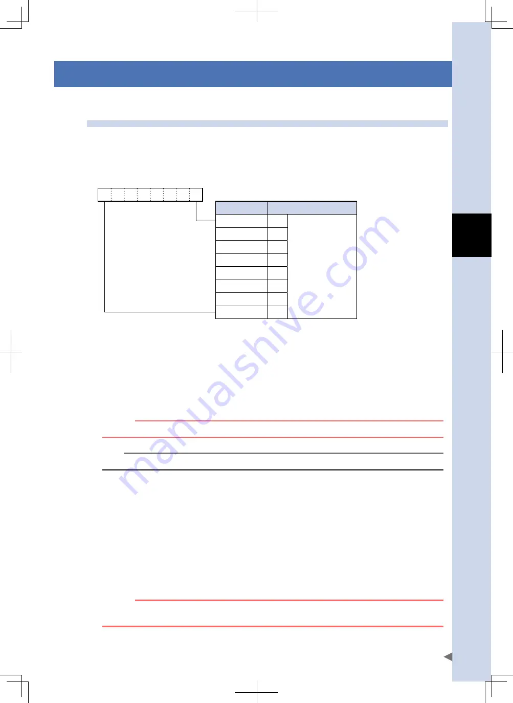
PIN0 to PIN7 (Point No. Select)
n
These inputs are read as 8-bit binary code Point Nos. when the START and TEACH commands are executed.
• Input example
PIN7
PIN0
0
0
1
0
1
0
0
1
Sum at ON
Example
2
0
1
Total = 41
(Point No.41)
2
1
0
2
2
0
2
3
8
2
4
0
2
5
32
2
6
0
2
7
0
JOG+ / JOG-
n
While this input is ON in the MANUAL mode, JOG movement to the specified direction's (+/-) soft limit occurs. When
this input switches OFF, a deceleration stop occurs. (See section 4.2, "JOG movement", in Chapter 5.)
SPD
n
Switches the overall positioning operation speed between two levels.
* Assigned to JOG+ terminal when "Speed switch function" (K17) is set to "Enable".
* This cannot be assigned when in MANUAL mode (MANUAL=ON).
c
CAutIoN
this function is available from controller's software version 1.06.111 onwards.
n
NOTE
Refer to section 3.8, "Speed switch function", in Chapter 5 for more details.
MANUAL
n
The MANUAL mode is established when this input switches ON. The MANUAL mode status is output to MANU-S.
ORG
n
This input executes a return-to-origin operation, thereby setting the robot's coordinates and enabling positioning
operations. The return-to-origin method varies according to the robot type and configuration. (See section 2, "Origin
search (return-to-origin)", in Chapter 5.)
/LOCK (interlock)
n
A deceleration stop occurs if this input switches OFF during operation. This input must be ON in order to operate the
robot.
w
WARNING
INtERloCkS ARE Not SAfEty INputS, AND ShoulD Not BE uSED foR SAfEty puRpoSES.
SERvoS Do Not SWItCh off EvEN If AN INtERloCk IS ApplIED.


