CYLINDER HEAD
5-12
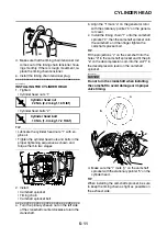
e. While holding the primary sheave nut with a
wrench, temporarily tighten the camshaft
sprocket bolt.
f. Remove the wire from the timing chain.
▲▲▲
▲
▲ ▲▲▲
▲
▲ ▲▲▲
▲
▲ ▲▲▲
▲
▲ ▲▲▲
▲
▲ ▲▲▲
▲
▲▲▲
3. Install:
• Timing chain tensioner gasket
• Timing chain tensioner
▼▼▼
▼
▼ ▼▼▼
▼
▼ ▼▼▼
▼
▼ ▼▼▼
▼
▼ ▼▼▼
▼
▼ ▼▼▼
▼
▼▼▼
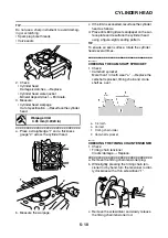
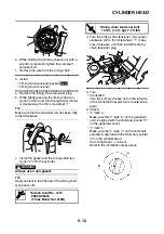
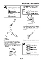
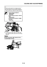
a. Remove the timing chain tensioner plug.
b. While lightly pressing the timing chain ten-
sioner rod by hand, turn the tensioner rod ful-
ly clockwise with a thin screwdriver “1”.
TIP
Make sure that the tensioner rod has been fully
turned clockwise.
c. Install the gasket and the timing chain ten-
sioner “2” onto the cylinder.
WARNING
EWA2DM1012
Always use a new gasket.
TIP
Apply sealant to the threads of the timing chain
tensioner bolts.
d. Turn the timing chain tensioner rod counter-
clockwise with a thin screwdriver “1”, make
sure it releases, and then install the timing
chain tensioner plug.
▲▲▲
▲
▲ ▲▲▲
▲
▲ ▲▲▲
▲
▲ ▲▲▲
▲
▲ ▲▲▲
▲
▲ ▲▲▲
▲
▲▲▲
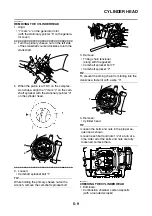
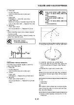
4. Turn:
• Crankshaft
(turn the primary sheave nut on the left side
of the crankshaft several turns counterclock-
wise)
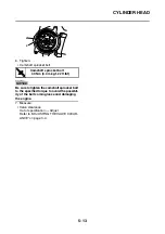
5. Check:
• “I” mark “a”
Make sure the “I” mark “a” on the generator
rotor is aligned with the stationary pointer “b”
on the generator cover.
• “I” mark “c”
Make sure the “I” mark “c” on the camshaft
sprocket is aligned with the stationary pointer
“d” on the cylinder head.
Out of alignment
→
Correct.
Refer to the installation steps above.
Yamaha bond No. 1215
90890-85505
(Three Bond No.1215®)
h
g
New
1
T
R
.
.
Timing chain tensioner bolt
10 Nm (1.0 m·kgf, 7.2 ft·lbf)
2
1
b
a
Summary of Contents for MBK XMAX 2014
Page 1: ...2014 SERVICE MANUAL YP125R YP125RA 2DM F8197 E0 ...
Page 6: ......
Page 8: ......
Page 64: ...TIGHTENING TORQUES 2 17 Muffler tightening sequence 1 2 3 ...
Page 72: ...LUBRICATION SYSTEM DIAGRAMS 2 25 EAS2DM1116 LUBRICATION SYSTEM DIAGRAMS 1 2 3 4 5 3 ...
Page 78: ...CABLE ROUTING 2 31 Steering head front view 1 2 3 4 5 6 8 8 A 7 7 ...
Page 80: ...CABLE ROUTING 2 33 Front brake left side view for YP125R 1 2 2 1 1 2 2 D E A B C ...
Page 82: ...CABLE ROUTING 2 35 Front brake left side view for YP125RA 2 1 1 2 1 2 2 A B D E C ...
Page 92: ...CABLE ROUTING 2 45 Frame right side view 3 2 4 1 2 3 A B 6 5 3 A B 3 3 2 3 3 A A B A B B 3 ...
Page 94: ...CABLE ROUTING 2 47 Engine right side view 6 6 6 6 C D C D D C 10 B 9 5 6 1 2 8 3 4 5 6 7 A ...
Page 98: ...CABLE ROUTING 2 51 Frame left side view C D C D 2 1 E 1 2 D C 6 1 4 5 3 2 1 7 3 2 1 A B ...
Page 100: ...CABLE ROUTING 2 53 Engine left side view 1 1 1 1 1 2 3 4 5 6 7 8 9 7 7 A B A B A B 1 ...
Page 106: ...CABLE ROUTING 2 59 Rear brake right side view 2 2 2 2 2 2 1 1 2 3 A B C 3 ...
Page 110: ...CABLE ROUTING 2 63 ...
Page 228: ...REAR SHOCK ABSORBER ASSEMBLIES AND SWINGARM 4 89 ...
Page 231: ......
Page 291: ...CRANKSHAFT 5 60 a 1 ...
Page 292: ...CRANKSHAFT 5 61 ...
Page 302: ...WATER PUMP 6 9 ...
Page 313: ......
Page 331: ...CHARGING SYSTEM 8 18 ...
Page 349: ...COOLING SYSTEM 8 36 ...
Page 391: ...FUEL PUMP SYSTEM 8 78 ...
Page 400: ...IMMOBILIZER SYSTEM 8 87 a Light on b Light off ...
Page 401: ...IMMOBILIZER SYSTEM 8 88 ...
Page 405: ...ABS ANTI LOCK BRAKE SYSTEM for YP125RA 8 92 ...
Page 439: ...ABS ANTI LOCK BRAKE SYSTEM for YP125RA 8 126 ...
Page 464: ...ELECTRICAL COMPONENTS 8 151 ...
Page 476: ......
Page 477: ......
Page 478: ......


