


FEATURES
1-2
EAS20170
FEATURES
EAS37P1140
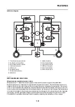
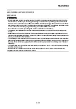
OUTLINE OF THE FI SYSTEM
The main function of a fuel supply system is to provide fuel to the combustion chamber at the optimum
air-fuel ratio in accordance with the engine operating conditions and the atmospheric temperature. In
the conventional carburetor system, the air-fuel ratio of the mixture that is supplied to the combustion
chamber is created by the volume of the intake air and the fuel that is metered by the jet used in the
respective carburetor.
Despite the same volume of intake air, the fuel volume requirement varies with the engine operating
conditions, such as acceleration, deceleration, or operating under a heavy load. Carburetors that meter
the fuel through the use of jets have been provided with various auxiliary devices, so that an optimum
air-fuel ratio can be achieved to accommodate the constant changes in the operating conditions of the
engine.
As the requirements for the engine to deliver more performance and cleaner exhaust gases increase,
it becomes necessary to control the air-fuel ratio in a more precise and finely tuned manner. To accom-
modate this need, this model has adopted an electronically controlled fuel injection (FI) system, in place
of the conventional carburetor system. This system can achieve an optimum air-fuel ratio required by
the engine at all times by using a microprocessor that regulates the fuel injection volume according to
the engine operating conditions detected by various sensors.
The adoption of the FI system has resulted in a highly precise fuel supply, improved engine response,
better fuel economy, and reduced exhaust emissions.
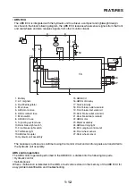
1
12
11
17
14 13
15
4 5 6
7,8,9 10
3
2
16
1. Air temperature sensor
2. Engine trouble warning light
3. ECU (engine control unit)
4. Spark plug
5. Fuel injector
6. Coolant temperature sensor
7. Intake air pressure sensor
8. Throttle position sensor
9. ISC (idle speed control) unit
10. Intake air temperature sensor
11. Crankshaft position sensor
12. O
2
sensor
13. Ignition coil
14. Fuel pump
15. Lean angle sensor
16. Front wheel sensor (for YP125RA)
17. Speed sensor (for YP125R)
Summary of Contents for MBK XMAX 2014
Page 1: ...2014 SERVICE MANUAL YP125R YP125RA 2DM F8197 E0 ...
Page 6: ......
Page 8: ......
Page 64: ...TIGHTENING TORQUES 2 17 Muffler tightening sequence 1 2 3 ...
Page 72: ...LUBRICATION SYSTEM DIAGRAMS 2 25 EAS2DM1116 LUBRICATION SYSTEM DIAGRAMS 1 2 3 4 5 3 ...
Page 78: ...CABLE ROUTING 2 31 Steering head front view 1 2 3 4 5 6 8 8 A 7 7 ...
Page 80: ...CABLE ROUTING 2 33 Front brake left side view for YP125R 1 2 2 1 1 2 2 D E A B C ...
Page 82: ...CABLE ROUTING 2 35 Front brake left side view for YP125RA 2 1 1 2 1 2 2 A B D E C ...
Page 92: ...CABLE ROUTING 2 45 Frame right side view 3 2 4 1 2 3 A B 6 5 3 A B 3 3 2 3 3 A A B A B B 3 ...
Page 94: ...CABLE ROUTING 2 47 Engine right side view 6 6 6 6 C D C D D C 10 B 9 5 6 1 2 8 3 4 5 6 7 A ...
Page 98: ...CABLE ROUTING 2 51 Frame left side view C D C D 2 1 E 1 2 D C 6 1 4 5 3 2 1 7 3 2 1 A B ...
Page 100: ...CABLE ROUTING 2 53 Engine left side view 1 1 1 1 1 2 3 4 5 6 7 8 9 7 7 A B A B A B 1 ...
Page 106: ...CABLE ROUTING 2 59 Rear brake right side view 2 2 2 2 2 2 1 1 2 3 A B C 3 ...
Page 110: ...CABLE ROUTING 2 63 ...
Page 228: ...REAR SHOCK ABSORBER ASSEMBLIES AND SWINGARM 4 89 ...
Page 231: ......
Page 291: ...CRANKSHAFT 5 60 a 1 ...
Page 292: ...CRANKSHAFT 5 61 ...
Page 302: ...WATER PUMP 6 9 ...
Page 313: ......
Page 331: ...CHARGING SYSTEM 8 18 ...
Page 349: ...COOLING SYSTEM 8 36 ...
Page 391: ...FUEL PUMP SYSTEM 8 78 ...
Page 400: ...IMMOBILIZER SYSTEM 8 87 a Light on b Light off ...
Page 401: ...IMMOBILIZER SYSTEM 8 88 ...
Page 405: ...ABS ANTI LOCK BRAKE SYSTEM for YP125RA 8 92 ...
Page 439: ...ABS ANTI LOCK BRAKE SYSTEM for YP125RA 8 126 ...
Page 464: ...ELECTRICAL COMPONENTS 8 151 ...
Page 476: ......
Page 477: ......
Page 478: ......


