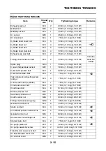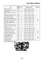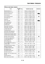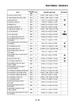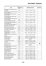
TIGHTENING TORQUES
2-21
TIP
Ring nut
1. Tighten the lower ring nut 38 Nm (3.8 m·kgf, 27 ft·lbf) with a torque wrench and the steering nut
wrench, and then loosen the nut 1/4 turn.
2. Tighten the lower ring nut 22 Nm (2.2 m·kgf, 16 ft·lbf) with a torque wrench and the steering nut
wrench.
3. Install the rubber washer and the center ring nut.
4. Finger tighten the center ring nut, align the slots of both ring nuts, and then install the lock washer.
5. Hold the lower and center ring nuts, and then tighten the upper ring nut 75 Nm (7.5 m·kgf, 54 ft·lbf)
with a torque wrench and the steering nut wrench.
TIP
Swingarm mounting bolt
1. Temporarily install the rear wheel axle nut “1”.
2. Temporarily install the swingarm mounting bolt (upper side) “2”, then the swingarm mounting bolt
(lower side) “3”.
3. Tighten the rear wheel axle nut to 135 Nm (13.5 m·kgf, 98 ft·lbf).
4. Tighten the swingarm mounting bolt (upper side), then the swingarm mounting bolt (lower side) to
28 Nm (2.8 m·kgf, 20 ft·lbf).
Swingarm tightening sequence:
Immobilizer screw
M5
2
4.0 Nm (0.40 m·kgf, 2.9 ft·lbf)
Battery terminal bolt
M5
2
7 Nm (0.7 m·kgf, 5.1 ft·lbf)
Starter relay bracket bolt
M6
1
4.0 Nm (0.40 m·kgf, 2.9 ft·lbf)
Starter relay terminal nut
M6
2
4.0 Nm (0.40 m·kgf, 2.9 ft·lbf)
Horn bolt
M6
1
10 Nm (1.0 m·kgf, 7.2 ft·lbf)
Hydraulic unit assembly bolt (for
YP125RA)
M6
3
7 Nm (0.7 m·kgf, 5.1 ft·lbf)
Brake hose union bolt (hydraulic
unit) (for YP125RA)
M10
4
30 Nm (3.0 m·kgf, 22 ft·lbf)
Brake hose (hydraulic unit to front
brake caliper) holder screw (for
YP125RA)
M6
1
9 Nm (0.9 m·kgf, 6.5 ft·lbf)
Item
Thread
size
Q’ty
Tightening torque
Remarks
1
2
3
Summary of Contents for MBK XMAX 2014
Page 1: ...2014 SERVICE MANUAL YP125R YP125RA 2DM F8197 E0 ...
Page 6: ......
Page 8: ......
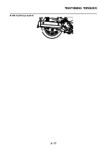
Page 64: ...TIGHTENING TORQUES 2 17 Muffler tightening sequence 1 2 3 ...
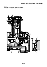
Page 72: ...LUBRICATION SYSTEM DIAGRAMS 2 25 EAS2DM1116 LUBRICATION SYSTEM DIAGRAMS 1 2 3 4 5 3 ...
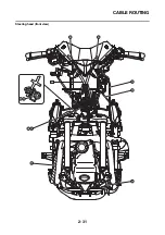
Page 78: ...CABLE ROUTING 2 31 Steering head front view 1 2 3 4 5 6 8 8 A 7 7 ...
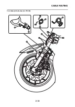
Page 80: ...CABLE ROUTING 2 33 Front brake left side view for YP125R 1 2 2 1 1 2 2 D E A B C ...
Page 82: ...CABLE ROUTING 2 35 Front brake left side view for YP125RA 2 1 1 2 1 2 2 A B D E C ...
Page 92: ...CABLE ROUTING 2 45 Frame right side view 3 2 4 1 2 3 A B 6 5 3 A B 3 3 2 3 3 A A B A B B 3 ...
Page 94: ...CABLE ROUTING 2 47 Engine right side view 6 6 6 6 C D C D D C 10 B 9 5 6 1 2 8 3 4 5 6 7 A ...
Page 98: ...CABLE ROUTING 2 51 Frame left side view C D C D 2 1 E 1 2 D C 6 1 4 5 3 2 1 7 3 2 1 A B ...
Page 100: ...CABLE ROUTING 2 53 Engine left side view 1 1 1 1 1 2 3 4 5 6 7 8 9 7 7 A B A B A B 1 ...
Page 106: ...CABLE ROUTING 2 59 Rear brake right side view 2 2 2 2 2 2 1 1 2 3 A B C 3 ...
Page 110: ...CABLE ROUTING 2 63 ...
Page 228: ...REAR SHOCK ABSORBER ASSEMBLIES AND SWINGARM 4 89 ...
Page 231: ......
Page 291: ...CRANKSHAFT 5 60 a 1 ...
Page 292: ...CRANKSHAFT 5 61 ...
Page 302: ...WATER PUMP 6 9 ...
Page 313: ......
Page 331: ...CHARGING SYSTEM 8 18 ...
Page 349: ...COOLING SYSTEM 8 36 ...
Page 391: ...FUEL PUMP SYSTEM 8 78 ...
Page 400: ...IMMOBILIZER SYSTEM 8 87 a Light on b Light off ...
Page 401: ...IMMOBILIZER SYSTEM 8 88 ...
Page 405: ...ABS ANTI LOCK BRAKE SYSTEM for YP125RA 8 92 ...
Page 439: ...ABS ANTI LOCK BRAKE SYSTEM for YP125RA 8 126 ...
Page 464: ...ELECTRICAL COMPONENTS 8 151 ...
Page 476: ......
Page 477: ......
Page 478: ......


