


ELECTRICAL COMPONENTS
8-138
TIP
Voltage should be measured 30 minutes after
the engine is stopped.
b. Connect a charger and ammeter to the bat-
tery and start charging.
TIP
Set the charging voltage to 16–17 V. If the set-
ting is lower, charging will be insufficient. If too
high, the battery will be over-charged.
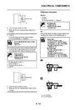
c. Make sure that the current is higher than the
standard charging current written on the bat-
tery.
TIP
If the current is lower than the standard charging
current written on the battery, set the charging
voltage adjust dial at 20–24 V and monitor the
amperage for 3–5 minutes to check the battery.
d. Adjust the voltage so that the current is at the
standard charging level.
e. Set the time according to the charging time
suitable for the open-circuit voltage.
f. If charging requires more than 5 hours, it is
advisable to check the charging current after
a lapse of 5 hours. If there is any change in
the amperage, readjust the voltage to obtain
the standard charging current.
g. Measure the battery open-circuit voltage after
leaving the battery unused for more than 30
minutes.
▲▲▲
▲
▲ ▲▲▲
▲
▲ ▲▲▲
▲
▲ ▲▲▲
▲
▲ ▲▲▲
▲
▲ ▲▲▲
▲
▲▲▲
▼▼▼
▼
▼ ▼▼▼
▼
▼ ▼▼▼
▼
▼ ▼▼▼
▼
▼ ▼▼▼
▼
▼ ▼▼▼
▼
▼▼▼
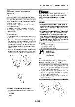
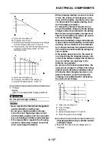
Charging method using a constant volt-
age charger
a. Measure the open-circuit voltage prior to
charging.
TIP
Voltage should be measured 30 minutes after
the engine is stopped.
b. Connect a charger and ammeter to the bat-
tery and start charging.
c. Make sure that the current is higher than the
standard charging current written on the bat-
tery.
TIP
If the current is lower than the standard charging
current written on the battery, this type of battery
charger cannot charge the VRLA (Valve Regu-
lated Lead Acid) battery. A variable voltage
charger is recommended.
d. Charge the battery until the battery’s charg-
ing voltage is 15 V.
TIP
Set the charging time at 20 hours (maximum).
e. Measure the battery open-circuit voltage after
leaving the battery unused for more than 30
minutes.
▲▲▲
▲
▲ ▲▲▲
▲
▲ ▲▲▲
▲
▲ ▲▲▲
▲
▲ ▲▲▲
▲
▲ ▲▲▲
▲
▲▲▲
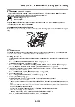
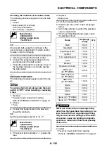
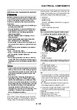
6. Install:
• Battery
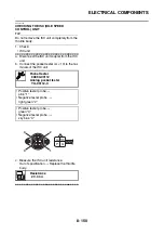
7. Connect:
• Battery leads
(to the battery terminals)
NOTICE
ECA13630
First, connect the positive battery lead “1”,
and then the negative battery lead “2”.
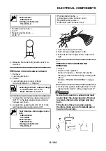
8. Check:
• Battery terminals
Dirt
→
Clean with a wire brush.
Loose connection
→
Connect properly.
9. Lubricate:
• Battery terminals
10.Install:
• Battery cover
• Standard charging current is reached
Battery is good.
• Standard charging current is not reached
Replace the battery.
12.8 V or more --- Charging is complete.
12.7 V or less --- Recharging is required.
Under 12.0 V --- Replace the battery.
12.8 V or more --- Charging is complete.
12.7 V or less --- Recharging is required.
Under 12.0 V --- Replace the battery.
Recommended lubricant
Dielectric grease
2
1
Summary of Contents for MBK XMAX 2014
Page 1: ...2014 SERVICE MANUAL YP125R YP125RA 2DM F8197 E0 ...
Page 6: ......
Page 8: ......
Page 64: ...TIGHTENING TORQUES 2 17 Muffler tightening sequence 1 2 3 ...
Page 72: ...LUBRICATION SYSTEM DIAGRAMS 2 25 EAS2DM1116 LUBRICATION SYSTEM DIAGRAMS 1 2 3 4 5 3 ...
Page 78: ...CABLE ROUTING 2 31 Steering head front view 1 2 3 4 5 6 8 8 A 7 7 ...
Page 80: ...CABLE ROUTING 2 33 Front brake left side view for YP125R 1 2 2 1 1 2 2 D E A B C ...
Page 82: ...CABLE ROUTING 2 35 Front brake left side view for YP125RA 2 1 1 2 1 2 2 A B D E C ...
Page 92: ...CABLE ROUTING 2 45 Frame right side view 3 2 4 1 2 3 A B 6 5 3 A B 3 3 2 3 3 A A B A B B 3 ...
Page 94: ...CABLE ROUTING 2 47 Engine right side view 6 6 6 6 C D C D D C 10 B 9 5 6 1 2 8 3 4 5 6 7 A ...
Page 98: ...CABLE ROUTING 2 51 Frame left side view C D C D 2 1 E 1 2 D C 6 1 4 5 3 2 1 7 3 2 1 A B ...
Page 100: ...CABLE ROUTING 2 53 Engine left side view 1 1 1 1 1 2 3 4 5 6 7 8 9 7 7 A B A B A B 1 ...
Page 106: ...CABLE ROUTING 2 59 Rear brake right side view 2 2 2 2 2 2 1 1 2 3 A B C 3 ...
Page 110: ...CABLE ROUTING 2 63 ...
Page 228: ...REAR SHOCK ABSORBER ASSEMBLIES AND SWINGARM 4 89 ...
Page 231: ......
Page 291: ...CRANKSHAFT 5 60 a 1 ...
Page 292: ...CRANKSHAFT 5 61 ...
Page 302: ...WATER PUMP 6 9 ...
Page 313: ......
Page 331: ...CHARGING SYSTEM 8 18 ...
Page 349: ...COOLING SYSTEM 8 36 ...
Page 391: ...FUEL PUMP SYSTEM 8 78 ...
Page 400: ...IMMOBILIZER SYSTEM 8 87 a Light on b Light off ...
Page 401: ...IMMOBILIZER SYSTEM 8 88 ...
Page 405: ...ABS ANTI LOCK BRAKE SYSTEM for YP125RA 8 92 ...
Page 439: ...ABS ANTI LOCK BRAKE SYSTEM for YP125RA 8 126 ...
Page 464: ...ELECTRICAL COMPONENTS 8 151 ...
Page 476: ......
Page 477: ......
Page 478: ......


