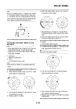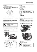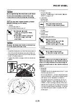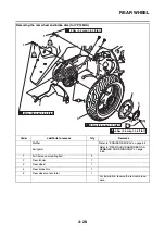
FRONT BRAKE
4-37
EAS22220
INTRODUCTION
WARNING
EWA14101
Disc brake components rarely require disas-
sembly. Therefore, always follow these pre-
ventive measures:
• Never disassemble brake components un-
less absolutely necessary.
• If any connection on the hydraulic brake
system is disconnected, the entire brake
system must be disassembled, drained,
cleaned, properly filled, and bled after reas-
sembly.
• Never use solvents on internal brake com-
ponents.
• Use only clean or new brake fluid for clean-
ing brake components.
• Brake fluid may damage painted surfaces
and plastic parts. Therefore, always clean
up any spilt brake fluid immediately.
• Avoid brake fluid coming into contact with
the eyes as it can cause serious injury.
FIRST AID FOR BRAKE FLUID ENTERING
THE EYES:
• Flush with water for 15 minutes and get im-
mediate medical attention.
EAS22230
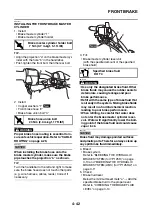
CHECKING THE FRONT BRAKE DISC
1. Remove:
• Front wheel
Refer to “FRONT WHEEL” on page 4-17.
2. Check:
• Brake disc
Damage/galling
→
Replace.
3. Measure:
• Brake disc deflection
Out of specification
→
Correct the brake disc
deflection or replace the brake disc.
▼▼▼
▼
▼ ▼▼▼
▼
▼ ▼▼▼
▼
▼ ▼▼▼
▼
▼ ▼▼▼
▼
▼ ▼▼▼
▼
▼▼▼
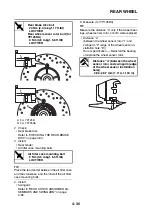
a. Place the vehicle on a suitable stand so that
the front wheel is elevated.
b. Before measuring the front brake disc deflec-
tion, turn the handlebar to the left or right to
ensure that the front wheel is stationary.
c. Remove the brake caliper.
d. Hold the dial gauge at a right angle against
the brake disc surface.
e. Measure the deflection 1.5 mm (0.06 in) be-
low the edge of the brake disc.
▲▲▲
▲
▲ ▲▲▲
▲
▲ ▲▲▲
▲
▲ ▲▲▲
▲
▲ ▲▲▲
▲
▲ ▲▲▲
▲
▲▲▲
4. Measure:
• Brake disc thickness
Measure the brake disc thickness at a few dif-
ferent locations.
Out of specification
→
Replace.
5. Adjust:
• Brake disc deflection
▼▼▼
▼
▼ ▼▼▼
▼
▼ ▼▼▼
▼
▼ ▼▼▼
▼
▼ ▼▼▼
▼
▼ ▼▼▼
▼
▼▼▼
a. Remove the brake disc.
b. Rotate the brake disc by one bolt hole.
c. Install the brake disc.
TIP
Tighten the brake disc bolts in stages and in a
crisscross pattern.
Brake disc deflection limit
0.15 mm (0.0059 in)
Brake disc thickness limit
4.5 mm (0.18 in)
T
R
.
.
Front brake disc bolt
12 Nm (1.2 m·kgf, 8.7 ft·lbf)
LOCTITE®
Summary of Contents for MBK XMAX 2014
Page 1: ...2014 SERVICE MANUAL YP125R YP125RA 2DM F8197 E0 ...
Page 6: ......
Page 8: ......
Page 64: ...TIGHTENING TORQUES 2 17 Muffler tightening sequence 1 2 3 ...
Page 72: ...LUBRICATION SYSTEM DIAGRAMS 2 25 EAS2DM1116 LUBRICATION SYSTEM DIAGRAMS 1 2 3 4 5 3 ...
Page 78: ...CABLE ROUTING 2 31 Steering head front view 1 2 3 4 5 6 8 8 A 7 7 ...
Page 80: ...CABLE ROUTING 2 33 Front brake left side view for YP125R 1 2 2 1 1 2 2 D E A B C ...
Page 82: ...CABLE ROUTING 2 35 Front brake left side view for YP125RA 2 1 1 2 1 2 2 A B D E C ...
Page 92: ...CABLE ROUTING 2 45 Frame right side view 3 2 4 1 2 3 A B 6 5 3 A B 3 3 2 3 3 A A B A B B 3 ...
Page 94: ...CABLE ROUTING 2 47 Engine right side view 6 6 6 6 C D C D D C 10 B 9 5 6 1 2 8 3 4 5 6 7 A ...
Page 98: ...CABLE ROUTING 2 51 Frame left side view C D C D 2 1 E 1 2 D C 6 1 4 5 3 2 1 7 3 2 1 A B ...
Page 100: ...CABLE ROUTING 2 53 Engine left side view 1 1 1 1 1 2 3 4 5 6 7 8 9 7 7 A B A B A B 1 ...
Page 106: ...CABLE ROUTING 2 59 Rear brake right side view 2 2 2 2 2 2 1 1 2 3 A B C 3 ...
Page 110: ...CABLE ROUTING 2 63 ...
Page 228: ...REAR SHOCK ABSORBER ASSEMBLIES AND SWINGARM 4 89 ...
Page 231: ......
Page 291: ...CRANKSHAFT 5 60 a 1 ...
Page 292: ...CRANKSHAFT 5 61 ...
Page 302: ...WATER PUMP 6 9 ...
Page 313: ......
Page 331: ...CHARGING SYSTEM 8 18 ...
Page 349: ...COOLING SYSTEM 8 36 ...
Page 391: ...FUEL PUMP SYSTEM 8 78 ...
Page 400: ...IMMOBILIZER SYSTEM 8 87 a Light on b Light off ...
Page 401: ...IMMOBILIZER SYSTEM 8 88 ...
Page 405: ...ABS ANTI LOCK BRAKE SYSTEM for YP125RA 8 92 ...
Page 439: ...ABS ANTI LOCK BRAKE SYSTEM for YP125RA 8 126 ...
Page 464: ...ELECTRICAL COMPONENTS 8 151 ...
Page 476: ......
Page 477: ......
Page 478: ......

