CRANKSHAFT
5-56
EAS2DM1075
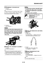
DISASSEMBLING THE CRANKCASE
1. Remove:
• Crankcase bolts
TIP
Loosen each bolt 1/4 of a turn at a time, in stag-
es and in a crisscross pattern. After all of the
bolts are fully loosened, remove them.
2. Remove:
• Left crankcase “1”
NOTICE
ECA2DM1037
Tap on one side of the crankcase with a soft-
face hammer. Tap only on the reinforced por-
tions of the crankcase, not on the crankcase
mating surfaces. Work slowly and carefully,
and make sure the crankcase halves sepa-
rate evenly.
EAS2DM1076
REMOVING THE CRANKSHAFT ASSEMBLY
1. Remove:
• Crankshaft assembly “1”
TIP
• Remove the crankshaft assembly with the
crankcase separating tool “2” and M6 bolts “3”.
• Make sure that the crankcase separating tool
is centered over the crankshaft assembly.
NOTICE
ECA2DM1038
• To protect the end of the crankshaft, place
an appropriate sized socket “4” between
the crankcase separating tool bolt and the
crankshaft.
• Do not tap on the crankshaft.
EAS2DM1077
CHECKING THE TIMING CHAIN AND TIMING
CHAIN GUIDE
1. Check:
• Timing chain
Damage/stiffness
→
Replace the timing
chain and camshaft sprocket as a set.
2. Check:
• Timing chain guide (intake side)
Damage/wear
→
Replace.
EAS2DM1078
CHECKING THE CRANKSHAFT AND
CONNECTING ROD
1. Measure:
• Crankshaft runout
Out of specification
→
Replace the crank-
shaft.
TIP
Turn the crankshaft slowly.
1
Crankcase separating tool
90890-01135
Crankcase separator
YU-01135-B
1
4
2
3
3
Summary of Contents for MBK XMAX 2014
Page 1: ...2014 SERVICE MANUAL YP125R YP125RA 2DM F8197 E0 ...
Page 6: ......
Page 8: ......
Page 64: ...TIGHTENING TORQUES 2 17 Muffler tightening sequence 1 2 3 ...
Page 72: ...LUBRICATION SYSTEM DIAGRAMS 2 25 EAS2DM1116 LUBRICATION SYSTEM DIAGRAMS 1 2 3 4 5 3 ...
Page 78: ...CABLE ROUTING 2 31 Steering head front view 1 2 3 4 5 6 8 8 A 7 7 ...
Page 80: ...CABLE ROUTING 2 33 Front brake left side view for YP125R 1 2 2 1 1 2 2 D E A B C ...
Page 82: ...CABLE ROUTING 2 35 Front brake left side view for YP125RA 2 1 1 2 1 2 2 A B D E C ...
Page 92: ...CABLE ROUTING 2 45 Frame right side view 3 2 4 1 2 3 A B 6 5 3 A B 3 3 2 3 3 A A B A B B 3 ...
Page 94: ...CABLE ROUTING 2 47 Engine right side view 6 6 6 6 C D C D D C 10 B 9 5 6 1 2 8 3 4 5 6 7 A ...
Page 98: ...CABLE ROUTING 2 51 Frame left side view C D C D 2 1 E 1 2 D C 6 1 4 5 3 2 1 7 3 2 1 A B ...
Page 100: ...CABLE ROUTING 2 53 Engine left side view 1 1 1 1 1 2 3 4 5 6 7 8 9 7 7 A B A B A B 1 ...
Page 106: ...CABLE ROUTING 2 59 Rear brake right side view 2 2 2 2 2 2 1 1 2 3 A B C 3 ...
Page 110: ...CABLE ROUTING 2 63 ...
Page 228: ...REAR SHOCK ABSORBER ASSEMBLIES AND SWINGARM 4 89 ...
Page 231: ......
Page 291: ...CRANKSHAFT 5 60 a 1 ...
Page 292: ...CRANKSHAFT 5 61 ...
Page 302: ...WATER PUMP 6 9 ...
Page 313: ......
Page 331: ...CHARGING SYSTEM 8 18 ...
Page 349: ...COOLING SYSTEM 8 36 ...
Page 391: ...FUEL PUMP SYSTEM 8 78 ...
Page 400: ...IMMOBILIZER SYSTEM 8 87 a Light on b Light off ...
Page 401: ...IMMOBILIZER SYSTEM 8 88 ...
Page 405: ...ABS ANTI LOCK BRAKE SYSTEM for YP125RA 8 92 ...
Page 439: ...ABS ANTI LOCK BRAKE SYSTEM for YP125RA 8 126 ...
Page 464: ...ELECTRICAL COMPONENTS 8 151 ...
Page 476: ......
Page 477: ......
Page 478: ......

