CAMSHAFT
5-15
EAS2DM1036
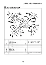
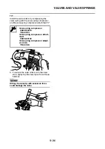
REMOVING THE CAMSHAFT
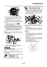
1. Remove:
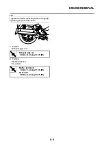
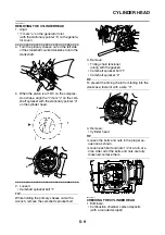
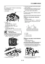
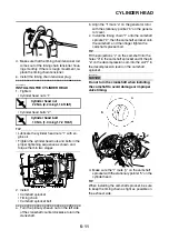
• Camshaft “1”
TIP
Screw an M8 bolt “2” into the threaded end of the
camshaft, and then pull out the camshaft.
EAS2DM1037
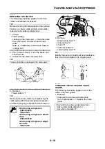
CHECKING THE CAMSHAFT
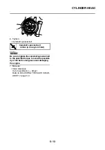
1. Check:
• Camshaft lobes
Blue discoloration/pitting/scratches
→
Re-
place the camshaft.
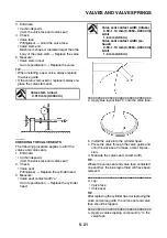
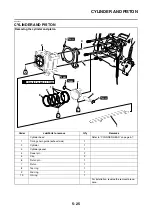
2. Measure:
• Camshaft lobe dimensions “a” and “b”
Out of specification
→
Replace the camshaft.
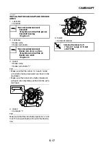
3. Check:
• Camshaft oil passage
Obstruction
→
Blow out with compressed air.
EAS2DM1038
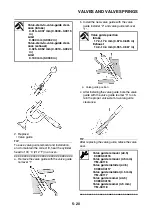
CHECKING THE DECOMPRESSION SYSTEM
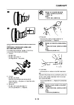
1. Check:
• Decompression system
▼▼▼
▼
▼ ▼▼▼
▼
▼ ▼▼▼
▼
▼ ▼▼▼
▼
▼ ▼▼▼
▼
▼ ▼▼▼
▼
▼▼▼
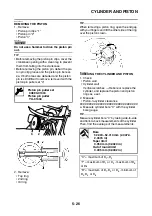
a. Check the decompression system with the
camshaft sprocket and the decompression
cam installed to the camshaft.
b. Check that the decompression lever “1”
moves smoothly.
c. Without operating the decompression lever,
check that the decompression cam “2”
projects from the camshaft (exhaust cam) as
shown in the illustration “A”.
d. Move the decompression lever in the direc-
tion of the arrow shown and check that the
decompression cam does not project from
the camshaft (exhaust cam) as shown in the
illustration “B”.
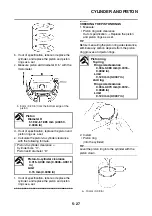
Camshaft lobe dimensions
Intake A
30.225–30.325 mm (1.1900–
1.1939 in)
Limit
30.125 mm (1.1860 in)
Intake B
25.064–25.164 mm (0.9868–
0.9907 in)
Limit
24.964 mm (0.9828 in)
Exhaust A
30.261–30.361 mm (1.1914–
1.1953 in)
Limit
30.161 mm (1.1874 in)
Exhaust B
25.121–25.221 mm (0.9890–
0.9930 in)
Limit
25.021 mm (0.9851 in)
1
2
1
Summary of Contents for MBK XMAX 2014
Page 1: ...2014 SERVICE MANUAL YP125R YP125RA 2DM F8197 E0 ...
Page 6: ......
Page 8: ......
Page 64: ...TIGHTENING TORQUES 2 17 Muffler tightening sequence 1 2 3 ...
Page 72: ...LUBRICATION SYSTEM DIAGRAMS 2 25 EAS2DM1116 LUBRICATION SYSTEM DIAGRAMS 1 2 3 4 5 3 ...
Page 78: ...CABLE ROUTING 2 31 Steering head front view 1 2 3 4 5 6 8 8 A 7 7 ...
Page 80: ...CABLE ROUTING 2 33 Front brake left side view for YP125R 1 2 2 1 1 2 2 D E A B C ...
Page 82: ...CABLE ROUTING 2 35 Front brake left side view for YP125RA 2 1 1 2 1 2 2 A B D E C ...
Page 92: ...CABLE ROUTING 2 45 Frame right side view 3 2 4 1 2 3 A B 6 5 3 A B 3 3 2 3 3 A A B A B B 3 ...
Page 94: ...CABLE ROUTING 2 47 Engine right side view 6 6 6 6 C D C D D C 10 B 9 5 6 1 2 8 3 4 5 6 7 A ...
Page 98: ...CABLE ROUTING 2 51 Frame left side view C D C D 2 1 E 1 2 D C 6 1 4 5 3 2 1 7 3 2 1 A B ...
Page 100: ...CABLE ROUTING 2 53 Engine left side view 1 1 1 1 1 2 3 4 5 6 7 8 9 7 7 A B A B A B 1 ...
Page 106: ...CABLE ROUTING 2 59 Rear brake right side view 2 2 2 2 2 2 1 1 2 3 A B C 3 ...
Page 110: ...CABLE ROUTING 2 63 ...
Page 228: ...REAR SHOCK ABSORBER ASSEMBLIES AND SWINGARM 4 89 ...
Page 231: ......
Page 291: ...CRANKSHAFT 5 60 a 1 ...
Page 292: ...CRANKSHAFT 5 61 ...
Page 302: ...WATER PUMP 6 9 ...
Page 313: ......
Page 331: ...CHARGING SYSTEM 8 18 ...
Page 349: ...COOLING SYSTEM 8 36 ...
Page 391: ...FUEL PUMP SYSTEM 8 78 ...
Page 400: ...IMMOBILIZER SYSTEM 8 87 a Light on b Light off ...
Page 401: ...IMMOBILIZER SYSTEM 8 88 ...
Page 405: ...ABS ANTI LOCK BRAKE SYSTEM for YP125RA 8 92 ...
Page 439: ...ABS ANTI LOCK BRAKE SYSTEM for YP125RA 8 126 ...
Page 464: ...ELECTRICAL COMPONENTS 8 151 ...
Page 476: ......
Page 477: ......
Page 478: ......

