


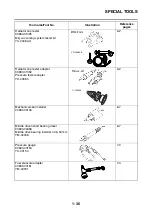


IMPORTANT INFORMATION
1-25
EAS20230
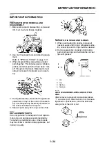
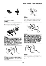
BEARINGS AND OIL SEALS
Install bearings “1” and oil seals “2” so that the
manufacturer’s marks or numbers are visible.
When installing oil seals, lubricate the oil seal
lips with a light coat of lithium-soap-based
grease. Oil bearings liberally when installing, if
appropriate.
NOTICE
ECA13300
Do not spin the bearing with compressed air
because this will damage the bearing surfac-
es.
EAS20240
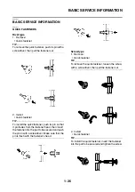
CIRCLIPS
Before reassembly, check all circlips carefully
and replace damaged or distorted circlips. Al-
ways replace piston pin clips after one use.
When installing a circlip “1”, make sure the
sharp-edged corner “2” is positioned opposite
the thrust “3” that the circlip receives.
EAS2DM1132
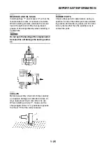
RUBBER PARTS
Check rubber parts for deterioration during in-
spection. Some of the rubber parts are sensitive
to gasoline, flammable oil, grease, etc. Do not al-
low any items other than the specified one to
contact the parts.
Summary of Contents for MBK XMAX 2014
Page 1: ...2014 SERVICE MANUAL YP125R YP125RA 2DM F8197 E0 ...
Page 6: ......
Page 8: ......
Page 64: ...TIGHTENING TORQUES 2 17 Muffler tightening sequence 1 2 3 ...
Page 72: ...LUBRICATION SYSTEM DIAGRAMS 2 25 EAS2DM1116 LUBRICATION SYSTEM DIAGRAMS 1 2 3 4 5 3 ...
Page 78: ...CABLE ROUTING 2 31 Steering head front view 1 2 3 4 5 6 8 8 A 7 7 ...
Page 80: ...CABLE ROUTING 2 33 Front brake left side view for YP125R 1 2 2 1 1 2 2 D E A B C ...
Page 82: ...CABLE ROUTING 2 35 Front brake left side view for YP125RA 2 1 1 2 1 2 2 A B D E C ...
Page 92: ...CABLE ROUTING 2 45 Frame right side view 3 2 4 1 2 3 A B 6 5 3 A B 3 3 2 3 3 A A B A B B 3 ...
Page 94: ...CABLE ROUTING 2 47 Engine right side view 6 6 6 6 C D C D D C 10 B 9 5 6 1 2 8 3 4 5 6 7 A ...
Page 98: ...CABLE ROUTING 2 51 Frame left side view C D C D 2 1 E 1 2 D C 6 1 4 5 3 2 1 7 3 2 1 A B ...
Page 100: ...CABLE ROUTING 2 53 Engine left side view 1 1 1 1 1 2 3 4 5 6 7 8 9 7 7 A B A B A B 1 ...
Page 106: ...CABLE ROUTING 2 59 Rear brake right side view 2 2 2 2 2 2 1 1 2 3 A B C 3 ...
Page 110: ...CABLE ROUTING 2 63 ...
Page 228: ...REAR SHOCK ABSORBER ASSEMBLIES AND SWINGARM 4 89 ...
Page 231: ......
Page 291: ...CRANKSHAFT 5 60 a 1 ...
Page 292: ...CRANKSHAFT 5 61 ...
Page 302: ...WATER PUMP 6 9 ...
Page 313: ......
Page 331: ...CHARGING SYSTEM 8 18 ...
Page 349: ...COOLING SYSTEM 8 36 ...
Page 391: ...FUEL PUMP SYSTEM 8 78 ...
Page 400: ...IMMOBILIZER SYSTEM 8 87 a Light on b Light off ...
Page 401: ...IMMOBILIZER SYSTEM 8 88 ...
Page 405: ...ABS ANTI LOCK BRAKE SYSTEM for YP125RA 8 92 ...
Page 439: ...ABS ANTI LOCK BRAKE SYSTEM for YP125RA 8 126 ...
Page 464: ...ELECTRICAL COMPONENTS 8 151 ...
Page 476: ......
Page 477: ......
Page 478: ......


