


REAR BRAKE
4-55
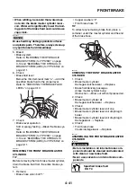
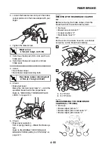
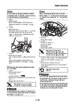
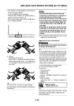
b. Loosen the bleed screw and push the brake
caliper pistons into the brake caliper with your
finger.
c. Tighten the bleed screw.
d. Install new brake pad shims onto each new
brake pad.
e. Install new brake pad supports and new
brake pads.
▲▲▲
▲
▲ ▲▲▲
▲
▲ ▲▲▲
▲
▲ ▲▲▲
▲
▲ ▲▲▲
▲
▲ ▲▲▲
▲
▲▲▲
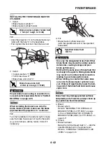
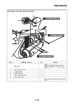
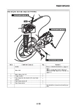
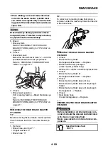
3. Install:
• Rear brake caliper
• Rear brake caliper retaining bolts
4. Check:
• Brake fluid level
Below the minimum level mark “a”
→
Add the
specified brake fluid to the proper level.
Refer to “CHECKING THE BRAKE FLUID
LEVEL” on page 3-10.
5. Check:
• Brake lever operation
Soft or spongy feeling
→
Bleed the brake sys-
tem.
Refer to “BLEEDING THE HYDRAULIC
BRAKE SYSTEM (ABS) (for YP125RA)” on
page 3-11.
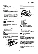
EAS2DM1009
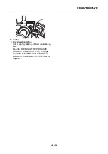
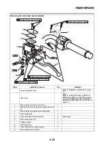
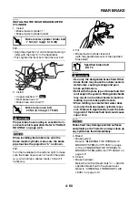
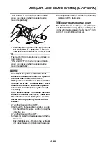
REMOVING THE REAR BRAKE CALIPER
TIP
Before removing the brake caliper, drain the
brake fluid from the entire brake system.
1. Remove:
• Brake hose union bolt “1”
• Copper washers “2”
• Rear brake hose “3”
TIP
Put the end of the brake hose into a container
and pump out the brake fluid carefully.
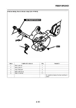
EAS2DM1011
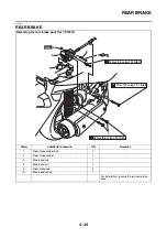
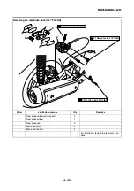
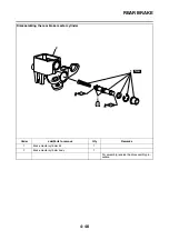
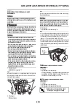
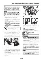
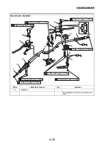
DISASSEMBLING THE REAR BRAKE
CALIPER (for YP125RA)
1. Remove:
• Brake caliper pistons “1”
• Brake caliper piston dust seals “2”
• Brake caliper piston seals “3”
T
R
.
.
Bleed screw
6 Nm (0.6 m·kgf, 4.3 ft·lbf)
T
R
.
.
Rear brake caliper retaining bolt
27 Nm (2.7 m·kgf, 20 ft·lbf)
2
1
a
A. For YP125R
B. For YP125RA
1
2
3
A
3
1
2
B
1
2
1
2
3
3
Summary of Contents for MBK XMAX 2014
Page 1: ...2014 SERVICE MANUAL YP125R YP125RA 2DM F8197 E0 ...
Page 6: ......
Page 8: ......
Page 64: ...TIGHTENING TORQUES 2 17 Muffler tightening sequence 1 2 3 ...
Page 72: ...LUBRICATION SYSTEM DIAGRAMS 2 25 EAS2DM1116 LUBRICATION SYSTEM DIAGRAMS 1 2 3 4 5 3 ...
Page 78: ...CABLE ROUTING 2 31 Steering head front view 1 2 3 4 5 6 8 8 A 7 7 ...
Page 80: ...CABLE ROUTING 2 33 Front brake left side view for YP125R 1 2 2 1 1 2 2 D E A B C ...
Page 82: ...CABLE ROUTING 2 35 Front brake left side view for YP125RA 2 1 1 2 1 2 2 A B D E C ...
Page 92: ...CABLE ROUTING 2 45 Frame right side view 3 2 4 1 2 3 A B 6 5 3 A B 3 3 2 3 3 A A B A B B 3 ...
Page 94: ...CABLE ROUTING 2 47 Engine right side view 6 6 6 6 C D C D D C 10 B 9 5 6 1 2 8 3 4 5 6 7 A ...
Page 98: ...CABLE ROUTING 2 51 Frame left side view C D C D 2 1 E 1 2 D C 6 1 4 5 3 2 1 7 3 2 1 A B ...
Page 100: ...CABLE ROUTING 2 53 Engine left side view 1 1 1 1 1 2 3 4 5 6 7 8 9 7 7 A B A B A B 1 ...
Page 106: ...CABLE ROUTING 2 59 Rear brake right side view 2 2 2 2 2 2 1 1 2 3 A B C 3 ...
Page 110: ...CABLE ROUTING 2 63 ...
Page 228: ...REAR SHOCK ABSORBER ASSEMBLIES AND SWINGARM 4 89 ...
Page 231: ......
Page 291: ...CRANKSHAFT 5 60 a 1 ...
Page 292: ...CRANKSHAFT 5 61 ...
Page 302: ...WATER PUMP 6 9 ...
Page 313: ......
Page 331: ...CHARGING SYSTEM 8 18 ...
Page 349: ...COOLING SYSTEM 8 36 ...
Page 391: ...FUEL PUMP SYSTEM 8 78 ...
Page 400: ...IMMOBILIZER SYSTEM 8 87 a Light on b Light off ...
Page 401: ...IMMOBILIZER SYSTEM 8 88 ...
Page 405: ...ABS ANTI LOCK BRAKE SYSTEM for YP125RA 8 92 ...
Page 439: ...ABS ANTI LOCK BRAKE SYSTEM for YP125RA 8 126 ...
Page 464: ...ELECTRICAL COMPONENTS 8 151 ...
Page 476: ......
Page 477: ......
Page 478: ......


