


FEATURES
1-7
WARNING
EWA2DM1010
The braking of the vehicle, even in the worst case, is principally executed when the vehicle is
advancing straight ahead. During a turn, sudden braking is liable to cause a loss of traction of
the tires. Even in vehicles equipped with ABS, overturning of the vehicle cannot be prevented
if it is braked suddenly.
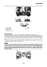
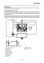
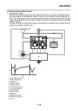
The ABS functions to prevent the tendency of the wheel to lock by controlling the brake fluid pressure.
However, if there is a tendency of the wheel to lock on a slippery road surface, due to engine braking,
the ABS may not be able to prevent the wheel from locking.
WARNING
EWA13870
The ABS controls only the tendency of the wheel to lock caused by applying the brakes. The
ABS cannot prevent wheel lock on slippery surfaces, such as ice, when it is caused by engine
braking, even if the ABS is operating.
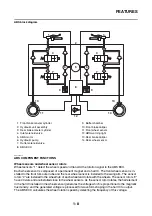
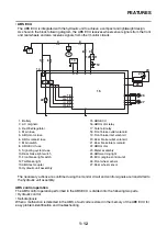
Electronic ABS features
The Yamaha ABS (anti-lock brake system) has been developed with the most advanced electronic
technology.
The ABS control is processed with good response under various vehicle travel conditions.
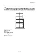
The ABS also includes a highly developed self-diagnosis function. The ABS detects any problem con-
dition and allows normal braking even if the ABS is not operating properly.
When this occurs, the ABS warning light on the meter assembly comes on.
The ABS stores the fault codes in the memory of the ABS ECU for easy problem identification and trou-
bleshooting.
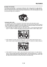
a. Friction force between the tire and road
surface
b. Brake force
c. Side force
d. Slip ratio (%)
Summary of Contents for MBK XMAX 2014
Page 1: ...2014 SERVICE MANUAL YP125R YP125RA 2DM F8197 E0 ...
Page 6: ......
Page 8: ......
Page 64: ...TIGHTENING TORQUES 2 17 Muffler tightening sequence 1 2 3 ...
Page 72: ...LUBRICATION SYSTEM DIAGRAMS 2 25 EAS2DM1116 LUBRICATION SYSTEM DIAGRAMS 1 2 3 4 5 3 ...
Page 78: ...CABLE ROUTING 2 31 Steering head front view 1 2 3 4 5 6 8 8 A 7 7 ...
Page 80: ...CABLE ROUTING 2 33 Front brake left side view for YP125R 1 2 2 1 1 2 2 D E A B C ...
Page 82: ...CABLE ROUTING 2 35 Front brake left side view for YP125RA 2 1 1 2 1 2 2 A B D E C ...
Page 92: ...CABLE ROUTING 2 45 Frame right side view 3 2 4 1 2 3 A B 6 5 3 A B 3 3 2 3 3 A A B A B B 3 ...
Page 94: ...CABLE ROUTING 2 47 Engine right side view 6 6 6 6 C D C D D C 10 B 9 5 6 1 2 8 3 4 5 6 7 A ...
Page 98: ...CABLE ROUTING 2 51 Frame left side view C D C D 2 1 E 1 2 D C 6 1 4 5 3 2 1 7 3 2 1 A B ...
Page 100: ...CABLE ROUTING 2 53 Engine left side view 1 1 1 1 1 2 3 4 5 6 7 8 9 7 7 A B A B A B 1 ...
Page 106: ...CABLE ROUTING 2 59 Rear brake right side view 2 2 2 2 2 2 1 1 2 3 A B C 3 ...
Page 110: ...CABLE ROUTING 2 63 ...
Page 228: ...REAR SHOCK ABSORBER ASSEMBLIES AND SWINGARM 4 89 ...
Page 231: ......
Page 291: ...CRANKSHAFT 5 60 a 1 ...
Page 292: ...CRANKSHAFT 5 61 ...
Page 302: ...WATER PUMP 6 9 ...
Page 313: ......
Page 331: ...CHARGING SYSTEM 8 18 ...
Page 349: ...COOLING SYSTEM 8 36 ...
Page 391: ...FUEL PUMP SYSTEM 8 78 ...
Page 400: ...IMMOBILIZER SYSTEM 8 87 a Light on b Light off ...
Page 401: ...IMMOBILIZER SYSTEM 8 88 ...
Page 405: ...ABS ANTI LOCK BRAKE SYSTEM for YP125RA 8 92 ...
Page 439: ...ABS ANTI LOCK BRAKE SYSTEM for YP125RA 8 126 ...
Page 464: ...ELECTRICAL COMPONENTS 8 151 ...
Page 476: ......
Page 477: ......
Page 478: ......


