


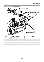

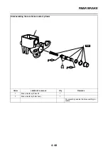
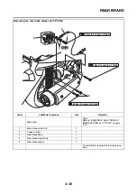
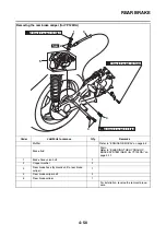


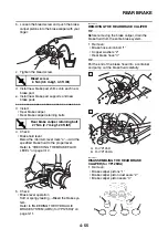

FRONT BRAKE
4-40
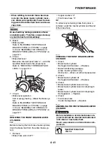
2. Check:
• Brake caliper bracket
Cracks/damage
→
Replace.
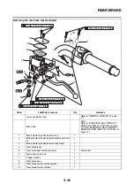
EAS22400
ASSEMBLING THE FRONT BRAKE CALIPER
WARNING
EWA37P1011
• Before installation, all internal brake com-
ponents should be cleaned and lubricated
with clean or new brake fluid.
• Never use solvents on internal brake com-
ponents as they will cause the brake caliper
piston dust seals and brake caliper piston
seals to swell and distort.
• Whenever a brake caliper is disassembled,
replace the brake caliper piston dust seals
and brake caliper piston seals.
EAS22420
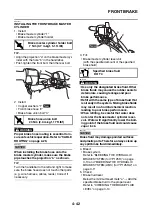
INSTALLING THE FRONT BRAKE CALIPER
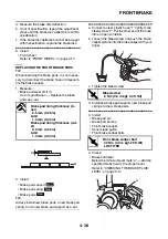
1. Install:
• Front brake caliper “1”
(temporarily)
• Copper washers “2”
• Front brake hose “3”
• Brake hose union bolt “4”
WARNING
EWA1SD1008
Proper brake hose routing is essential to in-
sure safe vehicle operation. Refer to “CABLE
ROUTING” on page 2-29.
NOTICE
ECA2DM1010
When installing the brake hose onto the
brake caliper, make sure the brake pipe “a”
touches the projection “b” on the brake cali-
per.
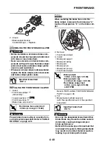
2. Remove:
• Front brake caliper
3. Install:
• Brake pad support
• Brake pad spring
• Brake pads
• Brake pad pin
• Brake pad pin cap
• Front brake caliper
Refer to “REPLACING THE FRONT BRAKE
PADS” on page 4-38.
4. Fill:
• Brake master cylinder reservoir
(with the specified amount of the specified
brake fluid)
WARNING
EWA37P1012
• Use only the designated brake fluid. Other
brake fluids may cause the rubber seals to
deteriorate, causing leakage and poor
brake performance.
• Refill with the same type of brake fluid that
is already in the system. Mixing brake fluids
may result in a harmful chemical reaction,
leading to poor brake performance.
Specified brake fluid
DOT 4
T
R
.
.
Front brake hose union bolt
23 Nm (2.3 m·kgf, 17 ft·lbf)
1
3
2
New
T
R
.
.
Brake pad pin
18 Nm (1.8 m·kgf, 13 ft·lbf)
Brake pad pin cap
2.5 Nm (0.25 m·kgf, 1.8 ft·lbf)
Front brake caliper bolt
40 Nm (4.0 m·kgf, 29 ft·lbf)
LOCTITE®
Specified brake fluid
DOT 4
b
a
1
2
3
4
New
Summary of Contents for MBK XMAX 2014
Page 1: ...2014 SERVICE MANUAL YP125R YP125RA 2DM F8197 E0 ...
Page 6: ......
Page 8: ......
Page 64: ...TIGHTENING TORQUES 2 17 Muffler tightening sequence 1 2 3 ...
Page 72: ...LUBRICATION SYSTEM DIAGRAMS 2 25 EAS2DM1116 LUBRICATION SYSTEM DIAGRAMS 1 2 3 4 5 3 ...
Page 78: ...CABLE ROUTING 2 31 Steering head front view 1 2 3 4 5 6 8 8 A 7 7 ...
Page 80: ...CABLE ROUTING 2 33 Front brake left side view for YP125R 1 2 2 1 1 2 2 D E A B C ...
Page 82: ...CABLE ROUTING 2 35 Front brake left side view for YP125RA 2 1 1 2 1 2 2 A B D E C ...
Page 92: ...CABLE ROUTING 2 45 Frame right side view 3 2 4 1 2 3 A B 6 5 3 A B 3 3 2 3 3 A A B A B B 3 ...
Page 94: ...CABLE ROUTING 2 47 Engine right side view 6 6 6 6 C D C D D C 10 B 9 5 6 1 2 8 3 4 5 6 7 A ...
Page 98: ...CABLE ROUTING 2 51 Frame left side view C D C D 2 1 E 1 2 D C 6 1 4 5 3 2 1 7 3 2 1 A B ...
Page 100: ...CABLE ROUTING 2 53 Engine left side view 1 1 1 1 1 2 3 4 5 6 7 8 9 7 7 A B A B A B 1 ...
Page 106: ...CABLE ROUTING 2 59 Rear brake right side view 2 2 2 2 2 2 1 1 2 3 A B C 3 ...
Page 110: ...CABLE ROUTING 2 63 ...
Page 228: ...REAR SHOCK ABSORBER ASSEMBLIES AND SWINGARM 4 89 ...
Page 231: ......
Page 291: ...CRANKSHAFT 5 60 a 1 ...
Page 292: ...CRANKSHAFT 5 61 ...
Page 302: ...WATER PUMP 6 9 ...
Page 313: ......
Page 331: ...CHARGING SYSTEM 8 18 ...
Page 349: ...COOLING SYSTEM 8 36 ...
Page 391: ...FUEL PUMP SYSTEM 8 78 ...
Page 400: ...IMMOBILIZER SYSTEM 8 87 a Light on b Light off ...
Page 401: ...IMMOBILIZER SYSTEM 8 88 ...
Page 405: ...ABS ANTI LOCK BRAKE SYSTEM for YP125RA 8 92 ...
Page 439: ...ABS ANTI LOCK BRAKE SYSTEM for YP125RA 8 126 ...
Page 464: ...ELECTRICAL COMPONENTS 8 151 ...
Page 476: ......
Page 477: ......
Page 478: ......


