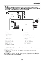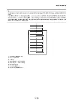
FEATURES
1-6
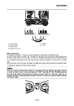
Wheel slip and hydraulic control
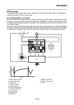
The ABS ECU calculates the wheel speed of each wheel according to the rotation signal received from
the front and rear wheel sensors. In addition, the ABS ECU calculates the vehicle chassis speed and
the rate of speed reduction based on the wheel speed values.
The difference between the chassis speed and the wheel speed calculated in the slip ratio formula is
equal to the wheel slip. When the wheel speed is suddenly reduced, the wheel has a tendency to lock.
When the wheel slip and the wheel speed reduction rate exceed the preset values, the ABS ECU de-
termines that the wheel has a tendency to lock.
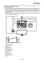
If the slip is large and the wheel has a tendency to lock (point “A” in the following figure), the ABS ECU
reduces the brake fluid pressure in the brake caliper. Once the ABS ECU determines that the tendency
of the wheel to lock has diminished after the brake fluid pressure is reduced, it increases the hydraulic
pressure (point “B” in the following figure). The hydraulic pressure is initially increased quickly, and then
it is increased gradually.
ABS operation and vehicle control
If the ABS starts operating, there is a tendency of the wheel to lock, and the vehicle is approaching the
limit of control. To make the rider aware of this condition, the ABS has been designed to generate a
reaction-force pulsating action in the front brake lever and rear brake lever independently.
TIP
When the ABS is activated, a pulsating action may be felt at the front brake lever or rear brake lever,
but this does not indicate a malfunction.
The higher the side force on a tire, the less traction there is available for braking. This is true whether
the vehicle is equipped with ABS or not. Therefore, sudden braking while cornering is not recommend-
ed. Excessive side force, which ABS cannot prevent, could cause the tire to slip sideways.
d
d
e
d
e
A
A
B
B
A
A
B
B
A
A
B
B
b
c
a
e
a. Chassis speed
b. Wheel speed
c. Brake force
d. Depressurizing phase
e. Pressurizing phase
Summary of Contents for MBK XMAX 2014
Page 1: ...2014 SERVICE MANUAL YP125R YP125RA 2DM F8197 E0 ...
Page 6: ......
Page 8: ......
Page 64: ...TIGHTENING TORQUES 2 17 Muffler tightening sequence 1 2 3 ...
Page 72: ...LUBRICATION SYSTEM DIAGRAMS 2 25 EAS2DM1116 LUBRICATION SYSTEM DIAGRAMS 1 2 3 4 5 3 ...
Page 78: ...CABLE ROUTING 2 31 Steering head front view 1 2 3 4 5 6 8 8 A 7 7 ...
Page 80: ...CABLE ROUTING 2 33 Front brake left side view for YP125R 1 2 2 1 1 2 2 D E A B C ...
Page 82: ...CABLE ROUTING 2 35 Front brake left side view for YP125RA 2 1 1 2 1 2 2 A B D E C ...
Page 92: ...CABLE ROUTING 2 45 Frame right side view 3 2 4 1 2 3 A B 6 5 3 A B 3 3 2 3 3 A A B A B B 3 ...
Page 94: ...CABLE ROUTING 2 47 Engine right side view 6 6 6 6 C D C D D C 10 B 9 5 6 1 2 8 3 4 5 6 7 A ...
Page 98: ...CABLE ROUTING 2 51 Frame left side view C D C D 2 1 E 1 2 D C 6 1 4 5 3 2 1 7 3 2 1 A B ...
Page 100: ...CABLE ROUTING 2 53 Engine left side view 1 1 1 1 1 2 3 4 5 6 7 8 9 7 7 A B A B A B 1 ...
Page 106: ...CABLE ROUTING 2 59 Rear brake right side view 2 2 2 2 2 2 1 1 2 3 A B C 3 ...
Page 110: ...CABLE ROUTING 2 63 ...
Page 228: ...REAR SHOCK ABSORBER ASSEMBLIES AND SWINGARM 4 89 ...
Page 231: ......
Page 291: ...CRANKSHAFT 5 60 a 1 ...
Page 292: ...CRANKSHAFT 5 61 ...
Page 302: ...WATER PUMP 6 9 ...
Page 313: ......
Page 331: ...CHARGING SYSTEM 8 18 ...
Page 349: ...COOLING SYSTEM 8 36 ...
Page 391: ...FUEL PUMP SYSTEM 8 78 ...
Page 400: ...IMMOBILIZER SYSTEM 8 87 a Light on b Light off ...
Page 401: ...IMMOBILIZER SYSTEM 8 88 ...
Page 405: ...ABS ANTI LOCK BRAKE SYSTEM for YP125RA 8 92 ...
Page 439: ...ABS ANTI LOCK BRAKE SYSTEM for YP125RA 8 126 ...
Page 464: ...ELECTRICAL COMPONENTS 8 151 ...
Page 476: ......
Page 477: ......
Page 478: ......


