


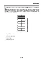

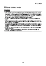


INSTRUMENT FUNCTIONS
1-19
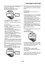
With the key in the “ON” position, the fuel meter
indicates the amount of fuel in the fuel tank. The
display segments of the fuel meter disappear to-
wards “E” (Empty) as the fuel level decreases.
When the fuel level reaches the bottom segment
near “E”, the bottom segment will flash. Refuel
as soon as possible.
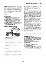
Clock
[To set the clock]
1. Push the “SELECT” button for 3 seconds,
and the hour digits will start flashing.
2. Use the “SELECT” button to set the hours.
3. Push the “SELECT” button for 3 seconds,
and the minute digits will start flashing.
4. Use the “SELECT” button to set the minutes.
5. Push the “SELECT” button for 3 seconds to
complete setting the clock.
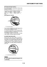
Odometer and tripmeter display
The odometer and tripmeter display is equipped
with the following:
• a tripmeter (which shows the distance traveled
since last set to zero)
• a time tripmeter (which shows the elapsed
riding time since last set to zero)
• a fuel reserve tripmeter (which shows the dis-
tance traveled since the fuel level warning light
came on)
• an oil change tripmeter (which shows the dis-
tance traveled since the last engine oil change)
• a V-belt replacement tripmeter (which shows
the distance traveled since the last V-belt re-
placement)
Pushing the “TRIP” button switches the display
between the odometer mode and the various
tripmeter modes in the following order:
Odo (odometer)
→
Trip (tripmeter)
→
Trip Time
(time tripmeter)
→
Oil (oil change tripmeter)
→
V-Belt (v-belt replacement tripmeter)
→
Odo
(odometer)
When approximately 2.5 L (0.66 US gal, 0.55
Imp.gal) of fuel remains in the fuel tank, the dis-
play will automatically change to the fuel reserve
tripmeter mode “F Trip” and start counting the
distance traveled from that point. In that case,
pushing the “TRIP” button switches the display
between the various tripmeter and odometer
modes in the following order:
Odo
→
Trip
→
Trip Time
→
F Trip (fuel reserve
tripmeter)
→
Oil Trip
→
V-Belt Trip
→
Odo
Oil Trip and V-Belt Trip display total distance
traveled from the first run or when the last reset
was done.
To reset a tripmeter, select it by pushing the
“TRIP” button until “Trip, Trip Time, F Trip” is dis-
played. While “Trip, Trip Time, F Trip” is dis-
played, push the “TRIP” button for 3 seconds. If
you do not reset the fuel reserve tripmeter man-
ually, it will reset itself automatically and the dis-
play will return to the prior mode after refueling
and traveling 5 km (3 mi).
TIP
The display cannot be changed back to “F Trip”
after it has been reset.
Oil change indicator “Oil”
This indicator flashes at the initial 1000 km (600
mi), then at 5000 km (3000 mi and every 6000
km (3500 mi thereafter to indicate that the en-
gine oil should be changed.
After changing the engine oil, reset the oil
change indicator.
[To reset the oil change indicator]
1. Turn the key to “ON”.
2. Push the “TRIP” button until “Oil” (oil change
tripmeter) is displayed in the odometer and
trip meter display. While “Oil” is displayed,
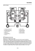
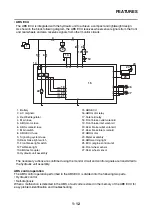
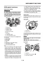
1. “TRIP/INFO” switch
2. Function display
C H
km
Odo
Air
Oil
V-Belt
Time
Trip
Odo
F
2
1
Summary of Contents for MBK XMAX 2014
Page 1: ...2014 SERVICE MANUAL YP125R YP125RA 2DM F8197 E0 ...
Page 6: ......
Page 8: ......
Page 64: ...TIGHTENING TORQUES 2 17 Muffler tightening sequence 1 2 3 ...
Page 72: ...LUBRICATION SYSTEM DIAGRAMS 2 25 EAS2DM1116 LUBRICATION SYSTEM DIAGRAMS 1 2 3 4 5 3 ...
Page 78: ...CABLE ROUTING 2 31 Steering head front view 1 2 3 4 5 6 8 8 A 7 7 ...
Page 80: ...CABLE ROUTING 2 33 Front brake left side view for YP125R 1 2 2 1 1 2 2 D E A B C ...
Page 82: ...CABLE ROUTING 2 35 Front brake left side view for YP125RA 2 1 1 2 1 2 2 A B D E C ...
Page 92: ...CABLE ROUTING 2 45 Frame right side view 3 2 4 1 2 3 A B 6 5 3 A B 3 3 2 3 3 A A B A B B 3 ...
Page 94: ...CABLE ROUTING 2 47 Engine right side view 6 6 6 6 C D C D D C 10 B 9 5 6 1 2 8 3 4 5 6 7 A ...
Page 98: ...CABLE ROUTING 2 51 Frame left side view C D C D 2 1 E 1 2 D C 6 1 4 5 3 2 1 7 3 2 1 A B ...
Page 100: ...CABLE ROUTING 2 53 Engine left side view 1 1 1 1 1 2 3 4 5 6 7 8 9 7 7 A B A B A B 1 ...
Page 106: ...CABLE ROUTING 2 59 Rear brake right side view 2 2 2 2 2 2 1 1 2 3 A B C 3 ...
Page 110: ...CABLE ROUTING 2 63 ...
Page 228: ...REAR SHOCK ABSORBER ASSEMBLIES AND SWINGARM 4 89 ...
Page 231: ......
Page 291: ...CRANKSHAFT 5 60 a 1 ...
Page 292: ...CRANKSHAFT 5 61 ...
Page 302: ...WATER PUMP 6 9 ...
Page 313: ......
Page 331: ...CHARGING SYSTEM 8 18 ...
Page 349: ...COOLING SYSTEM 8 36 ...
Page 391: ...FUEL PUMP SYSTEM 8 78 ...
Page 400: ...IMMOBILIZER SYSTEM 8 87 a Light on b Light off ...
Page 401: ...IMMOBILIZER SYSTEM 8 88 ...
Page 405: ...ABS ANTI LOCK BRAKE SYSTEM for YP125RA 8 92 ...
Page 439: ...ABS ANTI LOCK BRAKE SYSTEM for YP125RA 8 126 ...
Page 464: ...ELECTRICAL COMPONENTS 8 151 ...
Page 476: ......
Page 477: ......
Page 478: ......


