VALVES AND VALVE SPRINGS
5-19
EAS37P1014
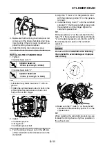
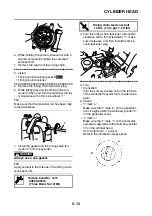
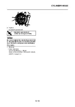
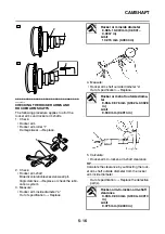
REMOVING THE VALVES
The following procedure applies to all of the
valves and related components.
TIP
Before removing the internal parts of the cylinder
head (e.g., valves, valve springs, valve seats),
make sure the valves properly seal.
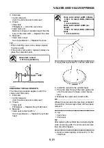
1. Check:
• Valve sealing
Leakage at the valve seat
→
Check the valve
face, valve seat, and valve seat contact
width.
Refer to “CHECKING THE VALVE SEATS”
on page 5-21.
▼▼▼
▼
▼ ▼▼▼
▼
▼ ▼▼▼
▼
▼ ▼▼▼
▼
▼ ▼▼▼
▼
▼ ▼▼▼
▼
▼▼▼
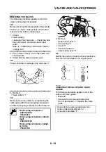
a. Pour a clean solvent “a” into the intake and
exhaust ports.
b. Check that the valves properly seal.
TIP
There should be no leakage at the valve seat “1”.
▲▲▲
▲
▲ ▲▲▲
▲
▲ ▲▲▲
▲
▲ ▲▲▲
▲
▲ ▲▲▲
▲
▲ ▲▲▲
▲
▲▲▲
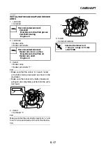
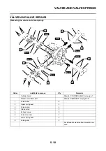
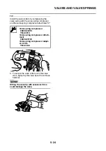
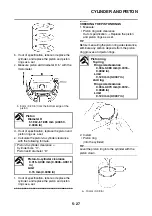
2. Remove:
• Valve cotters “1”
TIP
Remove the valve cotters by compressing the
valve spring with the valve spring compressor
and the valve spring compressor attachment “2”.
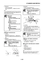
3. Remove:
• Upper spring seat “1”
• Valve spring “2”
• Valve “3”
• Valve stem seal “4”
• Lower spring seat “5”
TIP
Identify the position of each part very carefully so
that it can be reinstalled in its original place.
EAS2DM1041
CHECKING THE VALVES AND VALVE
GUIDES
The following procedure applies to all of the
valves and valve guides.
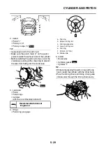
1. Measure:
• Valve-stem-to-valve-guide clearance
Out of specification
→
Replace the valve
guide.
Valve spring compressor
90890-04019
YM-04019
Valve spring compressor attach-
ment
90890-04108
Valve spring compressor adapt-
er 22 mm
YM-04108
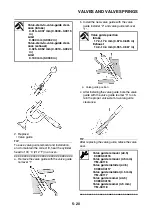
• Valve-stem-to-valve-guide clearance =
Valve guide inside diameter “a” -
Valve stem diameter “b”
2
1
Summary of Contents for MBK XMAX 2014
Page 1: ...2014 SERVICE MANUAL YP125R YP125RA 2DM F8197 E0 ...
Page 6: ......
Page 8: ......
Page 64: ...TIGHTENING TORQUES 2 17 Muffler tightening sequence 1 2 3 ...
Page 72: ...LUBRICATION SYSTEM DIAGRAMS 2 25 EAS2DM1116 LUBRICATION SYSTEM DIAGRAMS 1 2 3 4 5 3 ...
Page 78: ...CABLE ROUTING 2 31 Steering head front view 1 2 3 4 5 6 8 8 A 7 7 ...
Page 80: ...CABLE ROUTING 2 33 Front brake left side view for YP125R 1 2 2 1 1 2 2 D E A B C ...
Page 82: ...CABLE ROUTING 2 35 Front brake left side view for YP125RA 2 1 1 2 1 2 2 A B D E C ...
Page 92: ...CABLE ROUTING 2 45 Frame right side view 3 2 4 1 2 3 A B 6 5 3 A B 3 3 2 3 3 A A B A B B 3 ...
Page 94: ...CABLE ROUTING 2 47 Engine right side view 6 6 6 6 C D C D D C 10 B 9 5 6 1 2 8 3 4 5 6 7 A ...
Page 98: ...CABLE ROUTING 2 51 Frame left side view C D C D 2 1 E 1 2 D C 6 1 4 5 3 2 1 7 3 2 1 A B ...
Page 100: ...CABLE ROUTING 2 53 Engine left side view 1 1 1 1 1 2 3 4 5 6 7 8 9 7 7 A B A B A B 1 ...
Page 106: ...CABLE ROUTING 2 59 Rear brake right side view 2 2 2 2 2 2 1 1 2 3 A B C 3 ...
Page 110: ...CABLE ROUTING 2 63 ...
Page 228: ...REAR SHOCK ABSORBER ASSEMBLIES AND SWINGARM 4 89 ...
Page 231: ......
Page 291: ...CRANKSHAFT 5 60 a 1 ...
Page 292: ...CRANKSHAFT 5 61 ...
Page 302: ...WATER PUMP 6 9 ...
Page 313: ......
Page 331: ...CHARGING SYSTEM 8 18 ...
Page 349: ...COOLING SYSTEM 8 36 ...
Page 391: ...FUEL PUMP SYSTEM 8 78 ...
Page 400: ...IMMOBILIZER SYSTEM 8 87 a Light on b Light off ...
Page 401: ...IMMOBILIZER SYSTEM 8 88 ...
Page 405: ...ABS ANTI LOCK BRAKE SYSTEM for YP125RA 8 92 ...
Page 439: ...ABS ANTI LOCK BRAKE SYSTEM for YP125RA 8 126 ...
Page 464: ...ELECTRICAL COMPONENTS 8 151 ...
Page 476: ......
Page 477: ......
Page 478: ......

