FRONT FORK
4-79
7. Fill:
• Front fork leg
(with the specified amount of the recom-
mended fork oil)
NOTICE
ECA14230
• Be sure to use the recommended fork oil.
Other oils may have an adverse effect on
front fork performance.
• When disassembling and assembling the
front fork leg, do not allow any foreign ma-
terial to enter the front fork.
8. After filling the front fork leg, slowly stroke the
inner tube “1” up and down (at least ten
times) to distribute the fork oil.
TIP
Be sure to stroke the inner tube slowly because
the fork oil may spurt out.
9. Before measuring the fork oil level, wait ten
minutes until the oil has settled and the air
bubbles have dispersed.
TIP
Be sure to bleed the front fork leg of any residual
air.
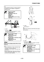
10.Measure:
• Front fork leg oil level “a”
(from the top of the inner tube, with the inner
tube fully compressed and without the fork
spring)
Out of specification
→
Correct.
TIP
• While filling the front fork leg, keep it upright.
• After filling, slowly pump the front fork leg up
and down to distribute the fork oil.
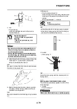
11.Install:
• Fork spring “1”
TIP
Install the fork spring with the smaller pitch “a”
facing down.
EAS23050
INSTALLING THE FRONT FORK LEGS
The following procedure applies to both of the
front fork legs.
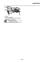
1. Install:
• Front fork leg “1”
WARNING
EWA37P1023
Make sure the brake hose is routed properly.
Recommended oil
Fork oil 10W or equivalent
Quantity
128.0 cm³ (4.33 US oz, 4.51
Imp.oz)
3
Level
109.0 mm (4.29 in)
1
a
Summary of Contents for MBK XMAX 2014
Page 1: ...2014 SERVICE MANUAL YP125R YP125RA 2DM F8197 E0 ...
Page 6: ......
Page 8: ......
Page 64: ...TIGHTENING TORQUES 2 17 Muffler tightening sequence 1 2 3 ...
Page 72: ...LUBRICATION SYSTEM DIAGRAMS 2 25 EAS2DM1116 LUBRICATION SYSTEM DIAGRAMS 1 2 3 4 5 3 ...
Page 78: ...CABLE ROUTING 2 31 Steering head front view 1 2 3 4 5 6 8 8 A 7 7 ...
Page 80: ...CABLE ROUTING 2 33 Front brake left side view for YP125R 1 2 2 1 1 2 2 D E A B C ...
Page 82: ...CABLE ROUTING 2 35 Front brake left side view for YP125RA 2 1 1 2 1 2 2 A B D E C ...
Page 92: ...CABLE ROUTING 2 45 Frame right side view 3 2 4 1 2 3 A B 6 5 3 A B 3 3 2 3 3 A A B A B B 3 ...
Page 94: ...CABLE ROUTING 2 47 Engine right side view 6 6 6 6 C D C D D C 10 B 9 5 6 1 2 8 3 4 5 6 7 A ...
Page 98: ...CABLE ROUTING 2 51 Frame left side view C D C D 2 1 E 1 2 D C 6 1 4 5 3 2 1 7 3 2 1 A B ...
Page 100: ...CABLE ROUTING 2 53 Engine left side view 1 1 1 1 1 2 3 4 5 6 7 8 9 7 7 A B A B A B 1 ...
Page 106: ...CABLE ROUTING 2 59 Rear brake right side view 2 2 2 2 2 2 1 1 2 3 A B C 3 ...
Page 110: ...CABLE ROUTING 2 63 ...
Page 228: ...REAR SHOCK ABSORBER ASSEMBLIES AND SWINGARM 4 89 ...
Page 231: ......
Page 291: ...CRANKSHAFT 5 60 a 1 ...
Page 292: ...CRANKSHAFT 5 61 ...
Page 302: ...WATER PUMP 6 9 ...
Page 313: ......
Page 331: ...CHARGING SYSTEM 8 18 ...
Page 349: ...COOLING SYSTEM 8 36 ...
Page 391: ...FUEL PUMP SYSTEM 8 78 ...
Page 400: ...IMMOBILIZER SYSTEM 8 87 a Light on b Light off ...
Page 401: ...IMMOBILIZER SYSTEM 8 88 ...
Page 405: ...ABS ANTI LOCK BRAKE SYSTEM for YP125RA 8 92 ...
Page 439: ...ABS ANTI LOCK BRAKE SYSTEM for YP125RA 8 126 ...
Page 464: ...ELECTRICAL COMPONENTS 8 151 ...
Page 476: ......
Page 477: ......
Page 478: ......


