


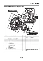


FRONT WHEEL
4-25
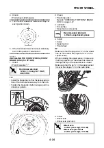
NOTICE
ECA37P1030
Before tightening the wheel axle, push down
hard on the handlebar several times and
check if the front fork rebounds smoothly.
EAS2DM1005
INSTALLING THE FRONT WHEEL (FRONT
BRAKE DISCS) (for YP125RA)
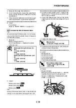
1. Install:
• Front brake disc “1”
• Front wheel sensor rotor “2”
NOTICE
ECA2DM1006
Replace the brake disc bolts and wheel sen-
sor rotor bolts with new ones.
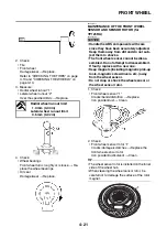
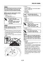
TIP
• Install the brake disc so that the recessed por-
tion of the bolt hole faces away from the hub.
• Install the wheel sensor rotor with the stamped
mark “a” facing outward.
• Tighten the bolts in stages and in a crisscross
pattern.
2. Check:
• Front brake disc
Refer to “CHECKING THE FRONT BRAKE
DISC” on page 4-37.
3. Lubricate:
• Wheel axle
• Oil seal lips
4. Install:
• Collars
• Front wheel
5. Install:
• Wheel axle
• Wheel axle pinch bolt
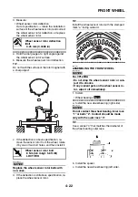
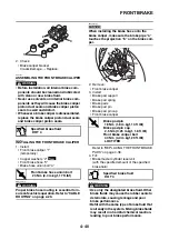
6. Install:
• Front wheel sensor
NOTICE
ECA2DM1007
Make sure there are no foreign materials in
the front wheel sensor rotor and front wheel
sensor. Foreign materials cause damage to
the front wheel sensor rotor and front wheel
sensor.
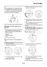
7. Measure:
• Distance
(between the front wheel sensor rotor “1” and
front wheel sensor “2”)
Out of specification
→
Check the wheel bear-
ing for looseness, and the front wheel sensor
and sensor rotor installation conditions
(warpage caused by overtorque, wrong in-
stallation direction, rotor decentering, LOC-
TITE® on the mounting surface of the rotor,
deformation caused by an impact during ser-
vice and caught foreign materials). If there is
any defective part, repair or replace the de-
fective part.
T
R
.
.
Front brake disc bolt
12 Nm (1.2 m·kgf, 8.7 ft·lbf)
LOCTITE®
Front wheel sensor rotor bolt
8 Nm (0.8 m·kgf, 5.8 ft·lbf)
LOCTITE®
a
2
1
Recommended lubricant
Lithium-soap-based grease
T
R
.
.
Wheel axle bolt
59 Nm (5.9 m·kgf, 43 ft·lbf)
Wheel axle pinch bolt
23 Nm (2.3 m·kgf, 17 ft·lbf)
T
R
.
.
Front wheel sensor bolt
8 Nm (0.8 m·kgf, 5.8 ft·lbf)
Summary of Contents for MBK XMAX 2014
Page 1: ...2014 SERVICE MANUAL YP125R YP125RA 2DM F8197 E0 ...
Page 6: ......
Page 8: ......
Page 64: ...TIGHTENING TORQUES 2 17 Muffler tightening sequence 1 2 3 ...
Page 72: ...LUBRICATION SYSTEM DIAGRAMS 2 25 EAS2DM1116 LUBRICATION SYSTEM DIAGRAMS 1 2 3 4 5 3 ...
Page 78: ...CABLE ROUTING 2 31 Steering head front view 1 2 3 4 5 6 8 8 A 7 7 ...
Page 80: ...CABLE ROUTING 2 33 Front brake left side view for YP125R 1 2 2 1 1 2 2 D E A B C ...
Page 82: ...CABLE ROUTING 2 35 Front brake left side view for YP125RA 2 1 1 2 1 2 2 A B D E C ...
Page 92: ...CABLE ROUTING 2 45 Frame right side view 3 2 4 1 2 3 A B 6 5 3 A B 3 3 2 3 3 A A B A B B 3 ...
Page 94: ...CABLE ROUTING 2 47 Engine right side view 6 6 6 6 C D C D D C 10 B 9 5 6 1 2 8 3 4 5 6 7 A ...
Page 98: ...CABLE ROUTING 2 51 Frame left side view C D C D 2 1 E 1 2 D C 6 1 4 5 3 2 1 7 3 2 1 A B ...
Page 100: ...CABLE ROUTING 2 53 Engine left side view 1 1 1 1 1 2 3 4 5 6 7 8 9 7 7 A B A B A B 1 ...
Page 106: ...CABLE ROUTING 2 59 Rear brake right side view 2 2 2 2 2 2 1 1 2 3 A B C 3 ...
Page 110: ...CABLE ROUTING 2 63 ...
Page 228: ...REAR SHOCK ABSORBER ASSEMBLIES AND SWINGARM 4 89 ...
Page 231: ......
Page 291: ...CRANKSHAFT 5 60 a 1 ...
Page 292: ...CRANKSHAFT 5 61 ...
Page 302: ...WATER PUMP 6 9 ...
Page 313: ......
Page 331: ...CHARGING SYSTEM 8 18 ...
Page 349: ...COOLING SYSTEM 8 36 ...
Page 391: ...FUEL PUMP SYSTEM 8 78 ...
Page 400: ...IMMOBILIZER SYSTEM 8 87 a Light on b Light off ...
Page 401: ...IMMOBILIZER SYSTEM 8 88 ...
Page 405: ...ABS ANTI LOCK BRAKE SYSTEM for YP125RA 8 92 ...
Page 439: ...ABS ANTI LOCK BRAKE SYSTEM for YP125RA 8 126 ...
Page 464: ...ELECTRICAL COMPONENTS 8 151 ...
Page 476: ......
Page 477: ......
Page 478: ......


