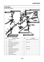


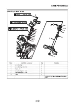


STEERING HEAD
4-83
EAS23110
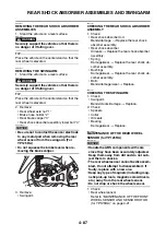
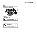
REMOVING THE LOWER BRACKET
1. Stand the vehicle on a level surface.
WARNING
EWA13120
Securely support the vehicle so that there is
no danger of it falling over.
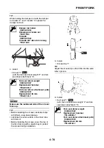
2. Remove:
• Upper ring nut “1”
• Lock washer
• Center ring nut
• Rubber washer
• Lower ring nut “2”
• Lower bracket
WARNING
EWA13730
Securely support the lower bracket so that
there is no danger of it falling.
TIP
Remove the upper ring nut and lower ring nut
with the steering nut wrench “3”.
EAS23120
CHECKING THE STEERING HEAD
1. Wash:
• Bearings
• Bearing races
2. Check:
• Bearings
• Bearing races
Damage/pitting
→
Replace.
3. Replace:
• Bearings
• Bearing races
▼▼▼
▼
▼ ▼▼▼
▼
▼ ▼▼▼
▼
▼ ▼▼▼
▼
▼ ▼▼▼
▼
▼ ▼▼▼
▼
▼▼▼
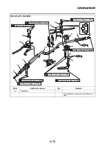
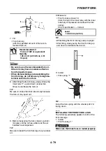
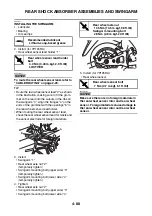
a. Remove the bearing races from the steering
head pipe “1” with a long rod “2” and hammer.
b. Remove the bearing race from the lower
bracket “3” with a floor chisel “4” and ham-
mer.
c. Install new bearing races.
NOTICE
ECA14270
If the bearing race is not installed properly,
the steering head pipe could be damaged.
TIP
Always replace the bearings and bearing races
as a set.
▲▲▲
▲
▲ ▲▲▲
▲
▲ ▲▲▲
▲
▲ ▲▲▲
▲
▲ ▲▲▲
▲
▲ ▲▲▲
▲
▲▲▲
4. Check:
• Lower handlebar holder
• Lower bracket
(along with the steering stem)
Bends/cracks/damage
→
Replace.
EAS23150
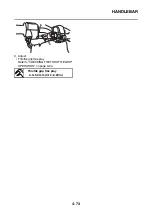
INSTALLING THE STEERING HEAD
1. Lubricate:
• Upper bearing
• Lower bearing
• Bearing races
2. Install:
• Lower ring nut “1”
Steering nut wrench
90890-01403
Exhaust flange nut wrench
YU-A9472
Recommended cleaning solvent
Kerosene
3
1
2
Recommended lubricant
Lithium-soap-based grease
Summary of Contents for MBK XMAX 2014
Page 1: ...2014 SERVICE MANUAL YP125R YP125RA 2DM F8197 E0 ...
Page 6: ......
Page 8: ......
Page 64: ...TIGHTENING TORQUES 2 17 Muffler tightening sequence 1 2 3 ...
Page 72: ...LUBRICATION SYSTEM DIAGRAMS 2 25 EAS2DM1116 LUBRICATION SYSTEM DIAGRAMS 1 2 3 4 5 3 ...
Page 78: ...CABLE ROUTING 2 31 Steering head front view 1 2 3 4 5 6 8 8 A 7 7 ...
Page 80: ...CABLE ROUTING 2 33 Front brake left side view for YP125R 1 2 2 1 1 2 2 D E A B C ...
Page 82: ...CABLE ROUTING 2 35 Front brake left side view for YP125RA 2 1 1 2 1 2 2 A B D E C ...
Page 92: ...CABLE ROUTING 2 45 Frame right side view 3 2 4 1 2 3 A B 6 5 3 A B 3 3 2 3 3 A A B A B B 3 ...
Page 94: ...CABLE ROUTING 2 47 Engine right side view 6 6 6 6 C D C D D C 10 B 9 5 6 1 2 8 3 4 5 6 7 A ...
Page 98: ...CABLE ROUTING 2 51 Frame left side view C D C D 2 1 E 1 2 D C 6 1 4 5 3 2 1 7 3 2 1 A B ...
Page 100: ...CABLE ROUTING 2 53 Engine left side view 1 1 1 1 1 2 3 4 5 6 7 8 9 7 7 A B A B A B 1 ...
Page 106: ...CABLE ROUTING 2 59 Rear brake right side view 2 2 2 2 2 2 1 1 2 3 A B C 3 ...
Page 110: ...CABLE ROUTING 2 63 ...
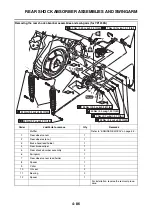
Page 228: ...REAR SHOCK ABSORBER ASSEMBLIES AND SWINGARM 4 89 ...
Page 231: ......
Page 291: ...CRANKSHAFT 5 60 a 1 ...
Page 292: ...CRANKSHAFT 5 61 ...
Page 302: ...WATER PUMP 6 9 ...
Page 313: ......
Page 331: ...CHARGING SYSTEM 8 18 ...
Page 349: ...COOLING SYSTEM 8 36 ...
Page 391: ...FUEL PUMP SYSTEM 8 78 ...
Page 400: ...IMMOBILIZER SYSTEM 8 87 a Light on b Light off ...
Page 401: ...IMMOBILIZER SYSTEM 8 88 ...
Page 405: ...ABS ANTI LOCK BRAKE SYSTEM for YP125RA 8 92 ...
Page 439: ...ABS ANTI LOCK BRAKE SYSTEM for YP125RA 8 126 ...
Page 464: ...ELECTRICAL COMPONENTS 8 151 ...
Page 476: ......
Page 477: ......
Page 478: ......


