


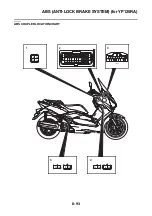


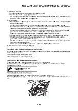


ABS (ANTI-LOCK BRAKE SYSTEM) (for YP125RA)
8-97
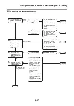
EAS27810
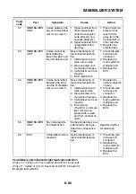
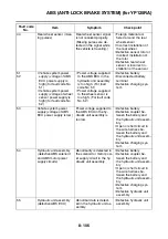
BASIC PROCESS FOR TROUBLESHOOTING
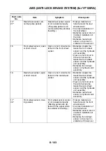
[A-1] Does only the ABS
warning light fail to
come on?
[A-2] Do all indicator lights
fail to come on?
The ABS warning light (LED)
is defective.
The wire harness is grounded
between the ABS ECU and the
meter assembly.
The meter assembly circuit is
defective.
The hydraulic unit assembly is
defective.
The main switch is defective.
The battery voltage is low.
The main fuse is blown.
The meter assembly circuit is
defective.
Yes
Yes
No
Return to [A].
Return to [A].
•
•
•
•
•
•
•
•
[A-3] The ABS warning light comes
on.
Connect the Yamaha
diagnostic tool, and then
perform troubleshooting.
Can the tool communicate with
the ABS ECU?
Return to [A].
[B-2] Diagnose by the fault
code.
[B-3] Delete the fault codes.
Return to [A].
[C-1] Perform the final checks.
Were all of the final checks
completed normally?
Finished.
Yes
No
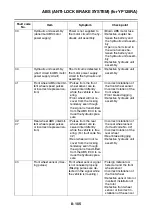
[A]
Turn the main switch to “ ON ”,
and check the ABS warning
light.
Fails to
come on
Comes on
The connection with the Yamaha
diagnostic tool is defective.
The ABS ECU fuse is blown.
The ABS ECU coupler is
disconnected.
•
•
•
The wire harness is defective.
•
The hydraulic unit assembly
is defective.
•
Cannot communicate
Can communicate
[B-1] Check for ABS fault
codes in the screen for the
Yamaha diagnostic tool.
Are fault codes displayed on
the screen?
No
Yes
(The ABS warning light
goes off when the light is
checked.)
The reaction force generated
during brake line routing
confirmation is incorrect.
Refer to “ [C-1] FINAL CHECK ”.
The brake hoses and brake
pipes are not connected
correctly.
•
The malfunction is not
corrected.
•
There is a break in the wire
harness between the ABS ECU
and the meter assembly.
•
The ABS warning light does
not go off when the light is
checked. Refer to “ [C-1]
FINAL CHECK ”.
The meter assembly circuit
is defective.
•
The ABS warning light circuit
in the hydraulic unit assembly
is defective.
•
Return to [A].
Summary of Contents for MBK XMAX 2014
Page 1: ...2014 SERVICE MANUAL YP125R YP125RA 2DM F8197 E0 ...
Page 6: ......
Page 8: ......
Page 64: ...TIGHTENING TORQUES 2 17 Muffler tightening sequence 1 2 3 ...
Page 72: ...LUBRICATION SYSTEM DIAGRAMS 2 25 EAS2DM1116 LUBRICATION SYSTEM DIAGRAMS 1 2 3 4 5 3 ...
Page 78: ...CABLE ROUTING 2 31 Steering head front view 1 2 3 4 5 6 8 8 A 7 7 ...
Page 80: ...CABLE ROUTING 2 33 Front brake left side view for YP125R 1 2 2 1 1 2 2 D E A B C ...
Page 82: ...CABLE ROUTING 2 35 Front brake left side view for YP125RA 2 1 1 2 1 2 2 A B D E C ...
Page 92: ...CABLE ROUTING 2 45 Frame right side view 3 2 4 1 2 3 A B 6 5 3 A B 3 3 2 3 3 A A B A B B 3 ...
Page 94: ...CABLE ROUTING 2 47 Engine right side view 6 6 6 6 C D C D D C 10 B 9 5 6 1 2 8 3 4 5 6 7 A ...
Page 98: ...CABLE ROUTING 2 51 Frame left side view C D C D 2 1 E 1 2 D C 6 1 4 5 3 2 1 7 3 2 1 A B ...
Page 100: ...CABLE ROUTING 2 53 Engine left side view 1 1 1 1 1 2 3 4 5 6 7 8 9 7 7 A B A B A B 1 ...
Page 106: ...CABLE ROUTING 2 59 Rear brake right side view 2 2 2 2 2 2 1 1 2 3 A B C 3 ...
Page 110: ...CABLE ROUTING 2 63 ...
Page 228: ...REAR SHOCK ABSORBER ASSEMBLIES AND SWINGARM 4 89 ...
Page 231: ......
Page 291: ...CRANKSHAFT 5 60 a 1 ...
Page 292: ...CRANKSHAFT 5 61 ...
Page 302: ...WATER PUMP 6 9 ...
Page 313: ......
Page 331: ...CHARGING SYSTEM 8 18 ...
Page 349: ...COOLING SYSTEM 8 36 ...
Page 391: ...FUEL PUMP SYSTEM 8 78 ...
Page 400: ...IMMOBILIZER SYSTEM 8 87 a Light on b Light off ...
Page 401: ...IMMOBILIZER SYSTEM 8 88 ...
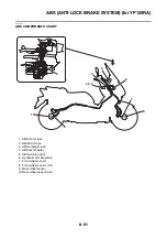
Page 405: ...ABS ANTI LOCK BRAKE SYSTEM for YP125RA 8 92 ...
Page 439: ...ABS ANTI LOCK BRAKE SYSTEM for YP125RA 8 126 ...
Page 464: ...ELECTRICAL COMPONENTS 8 151 ...
Page 476: ......
Page 477: ......
Page 478: ......


