FRONT WHEEL
4-22
3. Measure:
• Wheel sensor rotor deflection
Out of specification
→
Clean the installation
surface of the wheel sensor rotor and correct
the wheel sensor rotor deflection, or replace
the wheel sensor rotor.
▼▼▼
▼
▼ ▼▼▼
▼
▼ ▼▼▼
▼
▼ ▼▼▼
▼
▼ ▼▼▼
▼
▼ ▼▼▼
▼
▼▼▼
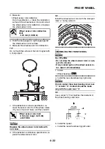
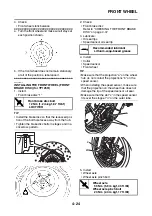
a. Hold the dial gauge at a right angle against
the wheel sensor rotor surface.
b. Measure the wheel sensor rotor deflection.
TIP
Do not touch the surface of the rotor magnet with
a sharp object.
c. If the deflection is above specification, re-
move the sensor rotor from the wheel, rotate
it by one or two bolt holes, and then install it.
NOTICE
ECA2DM1005
Replace the wheel sensor rotor bolts with
new ones.
d. If the deflection is still above specification, re-
place the wheel sensor rotor.
TIP
Install the wheel sensor rotor with the stamped
mark “a” facing outward.
▲▲▲
▲
▲ ▲▲▲
▲
▲ ▲▲▲
▲
▲ ▲▲▲
▲
▲ ▲▲▲
▲
▲ ▲▲▲
▲
▲▲▲
EAS21960
ASSEMBLING THE FRONT WHEEL
NOTICE
ECA2DM1042
For YP125RA
• Do not drop the wheel sensor rotor or sub-
ject it to shocks.
• If any solvent gets on the wheel sensor ro-
tor, wipe it off immediately.
1. Install:
• Wheel bearings
▼▼▼
▼
▼ ▼▼▼
▼
▼ ▼▼▼
▼
▼ ▼▼▼
▼
▼ ▼▼▼
▼
▼ ▼▼▼
▼
▼▼▼
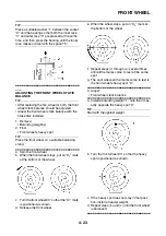
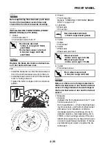
a. Install the new wheel bearing (right side).
NOTICE
ECA37P1029
Do not contact the wheel bearing inner race
“1” or balls “2”. Contact should be made
only with the outer race “3”.
TIP
Use a socket “4” that matches the diameter of
the wheel bearing outer race.
b. Install the spacer.
c. Install the new wheel bearing (left side).
Wheel sensor rotor deflection
limit
0.25 mm (0.0098 in)
T
R
.
.
Wheel sensor rotor bolt
8 Nm (0.8 m·kgf, 5.8 ft·lbf)
LOCTITE®
a
B
New
Summary of Contents for MBK XMAX 2014
Page 1: ...2014 SERVICE MANUAL YP125R YP125RA 2DM F8197 E0 ...
Page 6: ......
Page 8: ......
Page 64: ...TIGHTENING TORQUES 2 17 Muffler tightening sequence 1 2 3 ...
Page 72: ...LUBRICATION SYSTEM DIAGRAMS 2 25 EAS2DM1116 LUBRICATION SYSTEM DIAGRAMS 1 2 3 4 5 3 ...
Page 78: ...CABLE ROUTING 2 31 Steering head front view 1 2 3 4 5 6 8 8 A 7 7 ...
Page 80: ...CABLE ROUTING 2 33 Front brake left side view for YP125R 1 2 2 1 1 2 2 D E A B C ...
Page 82: ...CABLE ROUTING 2 35 Front brake left side view for YP125RA 2 1 1 2 1 2 2 A B D E C ...
Page 92: ...CABLE ROUTING 2 45 Frame right side view 3 2 4 1 2 3 A B 6 5 3 A B 3 3 2 3 3 A A B A B B 3 ...
Page 94: ...CABLE ROUTING 2 47 Engine right side view 6 6 6 6 C D C D D C 10 B 9 5 6 1 2 8 3 4 5 6 7 A ...
Page 98: ...CABLE ROUTING 2 51 Frame left side view C D C D 2 1 E 1 2 D C 6 1 4 5 3 2 1 7 3 2 1 A B ...
Page 100: ...CABLE ROUTING 2 53 Engine left side view 1 1 1 1 1 2 3 4 5 6 7 8 9 7 7 A B A B A B 1 ...
Page 106: ...CABLE ROUTING 2 59 Rear brake right side view 2 2 2 2 2 2 1 1 2 3 A B C 3 ...
Page 110: ...CABLE ROUTING 2 63 ...
Page 228: ...REAR SHOCK ABSORBER ASSEMBLIES AND SWINGARM 4 89 ...
Page 231: ......
Page 291: ...CRANKSHAFT 5 60 a 1 ...
Page 292: ...CRANKSHAFT 5 61 ...
Page 302: ...WATER PUMP 6 9 ...
Page 313: ......
Page 331: ...CHARGING SYSTEM 8 18 ...
Page 349: ...COOLING SYSTEM 8 36 ...
Page 391: ...FUEL PUMP SYSTEM 8 78 ...
Page 400: ...IMMOBILIZER SYSTEM 8 87 a Light on b Light off ...
Page 401: ...IMMOBILIZER SYSTEM 8 88 ...
Page 405: ...ABS ANTI LOCK BRAKE SYSTEM for YP125RA 8 92 ...
Page 439: ...ABS ANTI LOCK BRAKE SYSTEM for YP125RA 8 126 ...
Page 464: ...ELECTRICAL COMPONENTS 8 151 ...
Page 476: ......
Page 477: ......
Page 478: ......


