


ABS (ANTI-LOCK BRAKE SYSTEM) (for YP125RA)
8-107
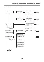
* The fault code number varies according to the vehicle conditions. For details, refer to the “Trouble-
shooting details”.
Troubleshooting details
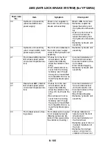
56
Hydraulic unit assembly
(abnormal internal power
supply)
Abnormality is detected in
the power supply circuit in
the hydraulic unit assem-
bly.
• Defective hydraulic unit
assembly
63
Front wheel sensor power
supply (voltage of power
supply is low)
Power voltage supplied
from the ABS ECU to the
front wheel sensor is too
low.
• Short circuit in the wire
harness between the
front wheel sensor and
the hydraulic unit assem-
bly
• Defective front wheel
sensor
• Defective hydraulic unit
assembly
64
Rear wheel sensor power
supply (voltage of power
supply is low)
Power voltage supplied
from the ABS ECU to the
rear wheel sensor is too
low.
• Short circuit in the wire
harness between the
rear wheel sensor and
the hydraulic unit assem-
bly
• Defective rear wheel
sensor
• Defective hydraulic unit
assembly
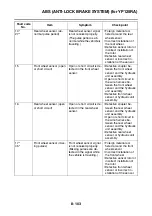
Fault code
No.
Item
Symptom
Check point
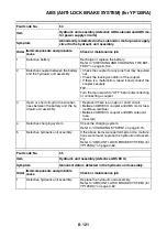
Fault code No.
11
25
Item
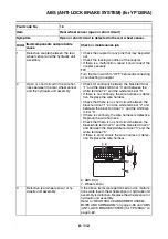
Front wheel sensor (intermittent pulses or no pulses)
Symptom
Front wheel sensor signal is not received properly. (Pulses are
not received or are received intermittently while the vehicle is
traveling.)
Order
Item/components and probable
cause
Check or maintenance job
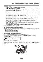
1
Foreign material adhered around the
front wheel sensor
Check the surface of the sensor rotor and wheel
sensor for foreign material, such as metal particles.
Clean the sensor rotor and wheel sensor if neces-
sary.
2
Incorrect installation of the front wheel Check the components for looseness, distortion,
and bends.
Refer to “CHECKING THE FRONT WHEEL” on
page 4-20.
3
Defective sensor rotor or incorrect in-
stallation of the rotor
Check the surface of the sensor rotor for damage.
Replace the sensor rotor if there is visible damage.
Refer to “MAINTENANCE OF THE FRONT
WHEEL SENSOR AND SENSOR ROTOR (for
YP125RA)” on page 4-21.
Summary of Contents for MBK XMAX 2014
Page 1: ...2014 SERVICE MANUAL YP125R YP125RA 2DM F8197 E0 ...
Page 6: ......
Page 8: ......
Page 64: ...TIGHTENING TORQUES 2 17 Muffler tightening sequence 1 2 3 ...
Page 72: ...LUBRICATION SYSTEM DIAGRAMS 2 25 EAS2DM1116 LUBRICATION SYSTEM DIAGRAMS 1 2 3 4 5 3 ...
Page 78: ...CABLE ROUTING 2 31 Steering head front view 1 2 3 4 5 6 8 8 A 7 7 ...
Page 80: ...CABLE ROUTING 2 33 Front brake left side view for YP125R 1 2 2 1 1 2 2 D E A B C ...
Page 82: ...CABLE ROUTING 2 35 Front brake left side view for YP125RA 2 1 1 2 1 2 2 A B D E C ...
Page 92: ...CABLE ROUTING 2 45 Frame right side view 3 2 4 1 2 3 A B 6 5 3 A B 3 3 2 3 3 A A B A B B 3 ...
Page 94: ...CABLE ROUTING 2 47 Engine right side view 6 6 6 6 C D C D D C 10 B 9 5 6 1 2 8 3 4 5 6 7 A ...
Page 98: ...CABLE ROUTING 2 51 Frame left side view C D C D 2 1 E 1 2 D C 6 1 4 5 3 2 1 7 3 2 1 A B ...
Page 100: ...CABLE ROUTING 2 53 Engine left side view 1 1 1 1 1 2 3 4 5 6 7 8 9 7 7 A B A B A B 1 ...
Page 106: ...CABLE ROUTING 2 59 Rear brake right side view 2 2 2 2 2 2 1 1 2 3 A B C 3 ...
Page 110: ...CABLE ROUTING 2 63 ...
Page 228: ...REAR SHOCK ABSORBER ASSEMBLIES AND SWINGARM 4 89 ...
Page 231: ......
Page 291: ...CRANKSHAFT 5 60 a 1 ...
Page 292: ...CRANKSHAFT 5 61 ...
Page 302: ...WATER PUMP 6 9 ...
Page 313: ......
Page 331: ...CHARGING SYSTEM 8 18 ...
Page 349: ...COOLING SYSTEM 8 36 ...
Page 391: ...FUEL PUMP SYSTEM 8 78 ...
Page 400: ...IMMOBILIZER SYSTEM 8 87 a Light on b Light off ...
Page 401: ...IMMOBILIZER SYSTEM 8 88 ...
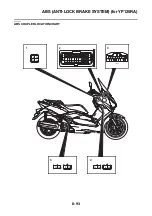
Page 405: ...ABS ANTI LOCK BRAKE SYSTEM for YP125RA 8 92 ...
Page 439: ...ABS ANTI LOCK BRAKE SYSTEM for YP125RA 8 126 ...
Page 464: ...ELECTRICAL COMPONENTS 8 151 ...
Page 476: ......
Page 477: ......
Page 478: ......


