


Traverse Installation and Commissioning Guide, Section 8: Network Interface Cabling Procedures
Insert an SFP into the SCM
Page 8-10
Turin Networks
Release TR3.2.1
inserted. To remove these SFPs, you grasp the SFP between thumb and forefinger,
pressing the latch to release it as you pull the SFP gently from the socket.
Figure 8-5 SFP with Bottom-Tab Latch
See the following topics for procedures on inserting and removing SFPs in the Traverse
shelf:
•
•
Insert an SFP
into the SCM
Follow these steps to insert SFPs into the GbE-10 SCM, keeping in mind that the
latches on your SFPs may vary slightly from the ones shown.
Important:
A properly grounded ESD wrist strap must be worn at all
times while handling SFPs.
Table 8-3 Insert an SFP into the SCM
Step
Procedure
1
Verify that the SFP is correct.
2
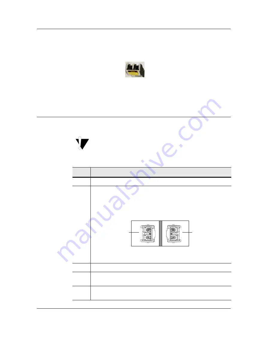
Orient the SFP into the SCM as shown in the figure below.
Note:
All SFP sockets are oriented either 90 degrees counter-clockwise
(odd numbered ports) or 90 degrees clockwise (even numbered ports) with
the top facing out from the SCM housing.
Figure 8-6 Example of SFPs with SCM Orientation
3
Move the bail clasp down to unlatch it before inserting it into the slot.
4
Slide the SFP into the slot and move the bail clasp up (or, depending on the
type of SFP, move it down) to secure it.
5
The Insert an SFP into the SCM procedure is complete. Continue to the
next procedure
Install Fiber Optic Cables at the SCM
Ports 1 & 2
Port 2
Port 1
TX
RX
TX
RX
Top of
SFP
Top of
SFP


