Connecting
Connecting digital sensors and actuators
32
Hans Turck GmbH & Co. KG | T +49 208 4952-0 | F +49 208 4952-264 | [email protected] | www.turck.com
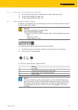
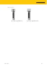
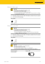
Fig. 39: TBEN-S1-4DXP, M8 connector for
connecting digital sensors and actuators,
C0 and C1
Fig. 40: TBEN-S1-4DXP, M8 connector for
connecting digital sensors and actuators,
C2 and C3
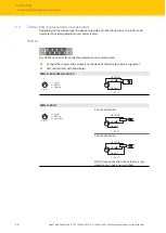
TBEN-S1-4DXP
3
1
4
v
1 = V
AUX1
3 = GND V1
4 = Signal In/Out
C0…C1
4 BK ( )
3 BU GND
1 BN (+)
Sensor
or
Actuator
v
C0...C3
3
1
4
v
1 = V
AUX2
3 = GND V2
4 = Signal In/Out
C2…C3
TBEN-S2-…
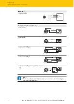
Fig. 41: M12 connector for connecting digital sensors and actuators
Connect the sensors and actuators to the device according to the pin assignment.
Seal unused slots with blind plugs.
TBEN-S2-8DIP
4
1
3
2
5
v
1 = V
aux
1
2 = Signal In
3 = GND V1
4 = Signal In
5 = FE
C0...C3
5 FE
4 BK
1 BN +
3 BU –
3 BU –
2 WH
v
C0...C3
Supply VAUX (pin1), switchable per connector
TBEN-S2-8DXP
4
1
3
2
5
v
1 = V
aux
1
2 = Signal In/Out
3 = GND V1
4 = Signal In/Out
5 = FE
C0...C1
5 FE
4 BK
1 BN +
3 BU –
3 BU –
2 WH
v
C0...C3
Sensor
or
Actuator
Sensor
or
Actuator
4
1
3
2
5
v
1 = V
aux
2
2 = Signal In/Out
3 = GND V2
4 = Signal In/Out
5 = FE
C2...C3
Supply VAUX (pin1), switchable per connector


