V04.00 | 2021/05
23
5.6.2
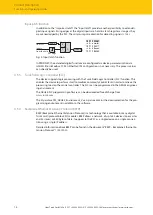
Fieldbus and I/O level shielding
The fieldbus and the I/O level of the TBEN-S modules can be grounded separately.
1
2
3
4
5
Fig. 22: Fieldbus and I/O level shielding
The grounding ring (2) and the grounding contact (4) are connected to each other and form
the module grounding. The shielding of the I/O level is permanently connected to the module
grounding. The module grounding is only connected to the reference potential of the installa-
tion when the module is mounted.
Shielding concept of the I/O modules (I/O level)
In the case of direct mounting on a mounting plate, the module grounding is connected to the
reference potential of the system via the metal screw in the lower mounting hole (3). If no mod-
ule grounding is desired, the electrical connection to the reference potential must be interrup-
ted, e.g. by mounting the device on an insulated mounting plate.
In the case of DIN rail mounting, the module earthing is led through the side grounding contact
(4) via connector TBNN-S0-DRS to the top-hat rail and connected to the reference potential of
the installation. If no module grounding is desired, the electrical connection to the reference
potential must be interrupted, e.g. by removing the grounding spring on the TBNN-S0-DRS.
Shielding concept of the fieldbus level
On delivery, a grounding clip (1) is provided on the connectors for the fieldbus connection (P1,
P2).
In the case of direct mounting on a mounting plate, the shielding of the fieldbus cables is
routed directly to the module grounding via the ground clip and the metal screw in the lower
mounting hole. In the case of DIN rail mounting, the shielding of the fieldbus cables is connec-
ted to the module grounding by the metal screw. The metal screw is supplied with the TBNN-
S0-DRS connector.
If direct grounding of the fieldbus shield is not desired, the grounding clip (1) must be re-
moved. In this case, the fieldbus shield is connected to the module ground via an RC element.

