background image


38 

RemotEye III User Manual – 62330-005 

Configuring the RemotEye III via HTTP 

The RemotEye III can be configured by opening a web session (e.g. Internet Explorer, Firefox, and Google Chrome). 

Hardware Setup 

Web configuration is accomplished through a network link.  Follow these steps to prepare the hardware for HTTP 
RemotEye III configuration: 

1.


Verify network cable connection to NETWORK port of RemotEye III.   

2.


Verify active link to LAN or Network.  

3.


For further information on the network connection, refer to “Making the Network Connection” on page 
18. 

Software Setup 

The web configuration is accomplished through a TCP/IP network connection.  A web connection can be established 
with RemotEye III by using any Internet Browser application (for example, Firefox).  Follow these steps to setup the 
software for web-based RemotEye III configuration:  

1.


Verify workstation is loaded with web browser application (e.g. Internet Explorer). 

2.


Verify a valid network path exists between RemotEye III  and the workstation.  If performing the web 
configuration from a workstation that is located on the same network, then proceed to the next section. 
Otherwise, refer back to the section entitled “Routing to the RemotEye III” on page 37. 

System Setup 

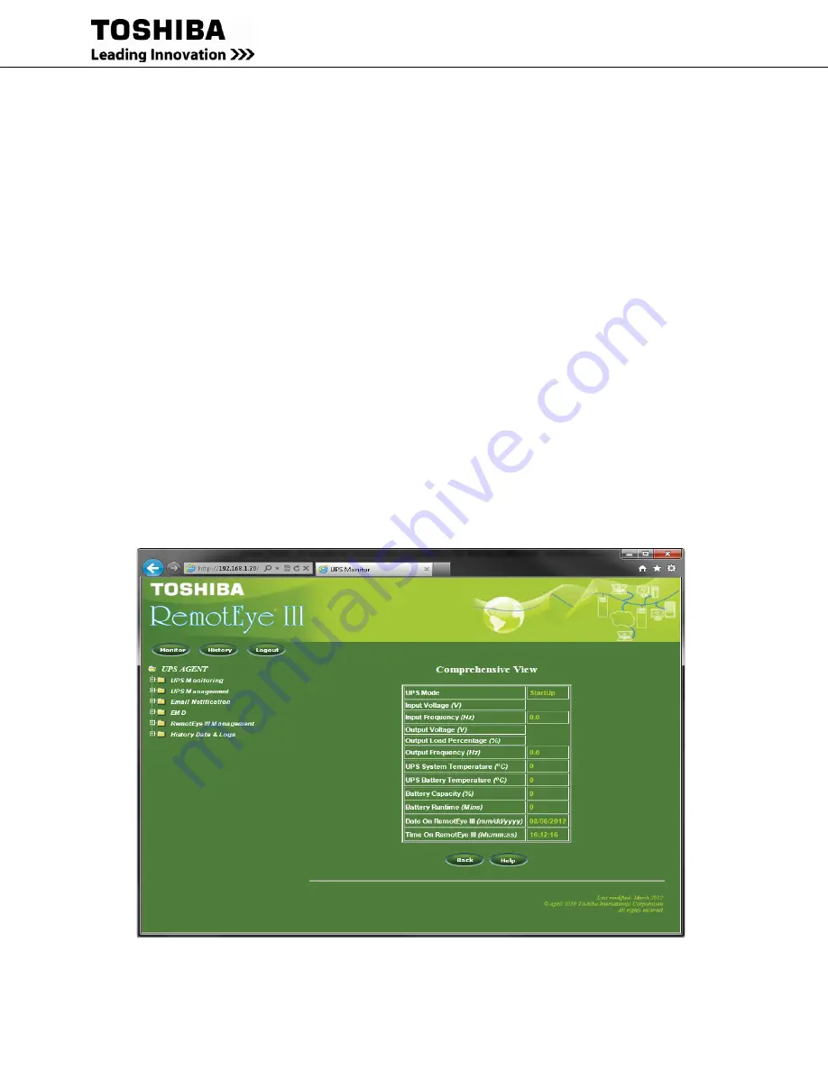
To access the RemotEye III via the web, enter the IP address of the RemotEye III in the URL field of the browser and 
press Enter (See Figure 29: RemotEye III with Internet Explorer Example). If unable to access the RemotEye III due 
to a firewall, contact the network administrator for information on bypassing the firewall of the LAN. 


Figure 29: RemotEye III with Internet Explorer Example 

Summary of Contents for RemotEye III

Page 1: ... ...

Page 2: ...RemotEye III User Manual 62330 005 RemotEye III User Manual Document Number 62330 005 August 2015 8 15 15 ...

Page 3: ...ling operating or performing maintenance on this equipment The information in this manual is subject to change without notice The Toshiba International Corporation shall not be liable for direct indirect special or consequential damages resulting from the use of the information contained within this manual This manual is copyrighted No part of this manual may be photocopied or reproduced in any fo...

Page 4: ...on information The Support Center can be reached at 877 867 8773 toll free or 713 466 0277 The center is open from 8 a m to 6 p m CST Monday through Friday Email us at toshibaups1 tic toshiba com You may also contact TOSHIBA by writing to TOSHIBA International Corporation UPS 13131 West Little York Road Houston Texas 77041 9990 For further information on TOSHIBA s products and services please visi...

Page 5: ...equipment damage or personal injury When used on UPS supporting safety critical equipment carefully analyze the impact of allowing remote access of the UPS control features Important Safety Instructions This manual contains important instructions that should be followed during the installation maintenance and operation of the UPS and its batteries to assure safe and proper operation Turn off locko...

Page 6: ...t safety information that must be carefully adhered to The word DANGER preceded by the safety alert symbol indicates that an imminently hazardous situation exists that if not avoided will result in death or serious injury to personnel The word WARNING in capital letters preceded by the safety alert symbol indicates that a potentially hazardous situation exists that if not avoided could result in d...

Page 7: ...ing Labels DO NOT attempt to install operate maintain or dispose of this equipment until you have read and understood all of the product warnings and user directions that are contained in this instruction manual DO NOT remove or cover any of the labels If the labels are damaged or if additional labels are required contact your Toshiba representative for additional labels Labels attached to the equ...

Page 8: ... that are subject to high humidity Do not install the unit in areas that allow exposure to direct sunlight Do not install the unit in areas that allow exposure to high levels of airborne dust metal particles or flammable gases Do not install the unit in areas near sources of electrical noise Do not install the unit in areas that would allow fluids or any foreign object to get inside the unit For f...

Page 9: ...rk Connection 18 Configuration 19 Configuring via Terminal 21 RemotEye III Configuration Menu Navigation 23 Configuring the RemotEye III via Telnet 36 Connecting to the RemotEye III via Telnet 37 RemotEye III Telnet Menu Navigation 37 Configuring the RemotEye III via HTTP 38 Connecting to the RemotEye III via HTTP 40 RemotEye III Web Menu Navigation 41 UPS Monitoring 41 UPS Management 61 Email Not...

Page 10: ...Jumper Setting 122 DIP Switch Setting 123 LAN connector J2 123 Console connector J3 123 Gold Finger GF1 124 Appendix A Install RemotEye Client Shutdown Software on VMware ESXi 5 125 Software Needed 125 Setup Procedure for RemotEye ESXi Client Shutdown Daemon 126 Appendix B Modbus Registers 132 Modbus Input Register for 1600XP MONITORING 132 Modbus Input Coil for 1600XP ALARMS and STATUS 143 Modbus...

Page 11: ...e RemotEye III The RemotEye III is a circuit board that is inserted into the option slot of the UPS The circuit board is connected to the UPS via the RemotEye III card edge connector Package Contents Listed below are the items included in the RemotEye III package 1 The RemotEye III printed circuit board 2 PC cable a DB9 female to RJ45 cable Workstation COM port to RemotEye III COM port 3 A CD ROM ...

Page 12: ...ayer SSL Configurations See Figure 2 HTTP Web Access Example Figure 2 HTTP Web Access Example SNMP Access RemotEye III provides enhanced SNMP security with option of SNMPv3 default protocol is SNMPv1 It is compatible with the United States Standard UPS MIB RFC1628 and Japanese Standard UPS MIB See SNMP example using iReasoning MIB Browser Software in Figure 3 SNMP Access Example Figure 3 SNMP Acce...

Page 13: ...e 4 Serial Communication Example Figure 4 Serial Communication Example Telnet Terminal Access Allow access to RemotEye III configuration settings through Telnet which includes Secure Shell SSH protocol This can be done using a Terminal Emulator Software such us HyperTerminal or Tera Term See Figure 5 Telnet Access Example Figure 5 Telnet Access Example Additional Features ...

Page 14: ...hen configuring the filtering settings it will affect both Email notifications and SNMP Traps Graphic User Interface GUI User friendly GUI on the web interface pages and Java applets Power Quality Monitor Java applets provide an on screen visual indication of power quality through its dynamic graphics See Figure 6 Java Applet Example Figure 6 Java Applet Example Versatile Remote UPS Management All...

Page 15: ...tors to automatically save history logs from one to multiple RemotEye IIIs at the same time to a computer s hard drive Toshiba Client Shutdown Software RemotEye III Windows Clients Shutdown Program is software that is installed onto the client s computer system This allows the RemotEye III to communicate with the Client Software to broadcast system failure messages via an IP Internet Protocol pack...

Page 16: ...tly or a Toshiba vendor for more information Figure 8 EMD Sensor Pack RemotRadar Software Sold Separately Is a real time monitoring solution software application that allows monitoring up to 5 000 RemotEye II IIIs all at once See Figure 9 RemotRadar Example It also has the ability to send SMS and Email notifications when an event occurs to one of the Toshiba UPS Please contact Toshiba directly or ...

Page 17: ...ll the RemotEye III card 1 Turn the UPS off using the proper shutdown procedure as explained in the UPS manual 2 Slide the RemotEye III printed circuit board into the extension option slot of the UPS 3 Secure the printed circuit board using the UPS supplied screws See Figure 10 RemotEye III Location in 1600XP UPS Figure 12 RemotEye III in 4300 UPS Figure 10 RemotEye III Location in 1600XP UPS ...

Page 18: ...II User Manual 62330 005 17 Figure 12 RemotEye III in 4300 UPS RemotEye III Located on Inside Left Door of 50kVA model RemotEye III Located on Deadfront of 15 30kVA model Figure 11 RemotEye III Location in 4200FA ...

Page 19: ...or computer A network administrator will need allocate an available port IP address 3 Verify a network link has been established Confirm the left most green LED is illuminated for 100Mbit s or right most amber LED is illuminated for 10Mbit s Note The RemotEye III s DHCP BOOTP setting comes enable by default If there is a DHCP BOOTP server within the network the DHCP BOOTP server will allocate leas...

Page 20: ... MAC Address Label Figure 14 RemotEye III MAC Address Label For each RemotEye III the MAC address is created using the following format 00 E0 D8 LL MM NN The first half of this code 00 E0 D8 identifies the manufacturer of the Ethernet board Since every RemotEye III is produced by the same manufacturer these 3 hexadecimal bytes remain constant The LL MM NN characters identify the serial number of t...

Page 21: ...red with a default Network Mask This default value is always 255 255 0 0 This places RemotEye III on a Class B network Default Gateway The RemotEye III is initially configured with a Gateway address of 0 0 0 0 This value indicates RemotEye III will not attempt to use a gateway ...

Page 22: ...orkstation COM port NOTE if no COM port is available use a USB to Serial RS 232 converter 2 Connect the RJ45 end of the PC cable to the COM port of RemotEye III RJ45 to DB9 Female Cable DB9 Female End RJ45 End Figure 15 Serial Communication Physical Connection Example Software Setup The direct communication can be performed from a workstation that is running a Terminal Emulator Software TES such a...

Page 23: ...Enter and the RemotEye III version and Password field will be displayed See Figure 16 RemotEye III retains the password of the UPS it is connected to If the RemotEye is brand new right out of the box the default password is ADMIN Password case sensitive ADMIN Once connected to the UPS RemotEye will try to verify the password by using the default There are two ways this password can be changed on t...

Page 24: ...y Address 3 Network Mask 4 Date and Time 5 Dump Modules CRC value 0 Return to Previous Menu 2 Control Group 1 HTTP Login Username 2 Community Read On1y 3 Community Read Write 4 BOOTP DHCP Control 5 Telnet Control 6 Network Upgrade Control 7 HTTP Security Control 8 SNMP Version Control 9 HTTP s Authentication 0 Return to Previous Menu 3 Parameter Group 1 System Contact 2 System Name 3 System Locati...

Page 25: ...urn to previous menu 0 Return to Previous Menu 2 SNMP Communities 1 Modify 2 Reset 0 Return to Previous Menu 3 SNMPV3 USM Table 1 Modify 2 Reset 0 Return to Previous Menu 4 Trap Receiver Table 1 Modify 2 Reset 0 Return to Previous Menu 5 Reset Configuration to Default Reset Configuration y n 6 Save and Exit 7 Save and Restart RemotEye III Restart Agent y n Table 1 Menu Map for RemotEye III Console...

Page 26: ...SNMPv3 USM Table 4 Trap Receiver Table 5 Reset Configuration to Default 6 Save and Exit 7 Save and Restart Agent Press the number of the associated selection and press Enter TIC RemotEye III Main Menu 1 TIC RemotEye III Configuration 2 SNMP Communities 3 SNMPV3 USM Table 4 Trap Receiver Table 5 Reset Configuration To Default 6 Save and Exit 7 Save and Restart Agent Please Enter Your Choice Figure ...

Page 27: ...n provides access to the following system settings 1 System Group 2 Control Group 3 Parameter Group 4 Email Group 5 EMD Group 6 Web Authentication Group 0 Return to Previous Menu TIC RemotEye III Configuration Menu 1 System Group 2 Control Group 3 Parameter Group 4 Email Group 5 EMD Group 6 Web Authenication Group 0 Return to previous menu Please Enter Your Choice Figure 18 Console Configuration M...

Page 28: ...ly RemotEye III supports the Network Time Protocol NTP and NTP These two features enable the UPS to synchronize its date and time with a NTP server See Figure 20 Date Time Menu Description 5 Dump modules CRC value 0 Return to Previous Menu System Group Menu RemotEye III Agent Version TIC RemotEye III v1 03 Ethernet address 00 E0 D8 08 80 0D 1 Ip Address 172 18 1 63 2 Gateway Address 172 18 1 1 3 N...

Page 29: ...meter is used to enable or disable the web password protection feature When enabled a password is required to access RemotEye III through the web and write privileges are automatically assumed When disabled any machine can access RemotEye III over the web but a password is required prior to assuming write privileges The default setting is Disabled 8 SNMP Version Control This parameter is used to e...

Page 30: ...nt Identifier CID in DHCP systems 3 System Location The RemotEye III physical location This string can be changed by administrator as desired 4 Poll Rate The polling rate in seconds This determines how frequently RemotEye III updates its data from the Toshiba UPS The default setting is 5 seconds 0 Return to previous menu Note System will label each event email with the system Name and Location in ...

Page 31: ...otEye III daily status report that are listed in the Mail Receivers setting 7 7 Mail Receivers This Parameter is used to enter up to four recipients email address and select the Mail Type for each recipient Here is the list on the three different Mail Types a None Disable option to send email to recipients b Events Current events will be sent to recipients c Events with Status Current events Histo...

Page 32: ...tions to setup the hysteresis and calibration offset from this group 3 Alarm 1 Group The Alarm 1 Group provides the option to setup this dry contact as normal close normal open high active low active and disabled 4 Alarm 2 Group The Alarm 2 Group provides the option to setup this dry contact as normal close normal open high active low active and disabled 5 Device Status The Device Status allows th...

Page 33: ...as follows IP Address IP address of the NMS Community String NMS Get Set Community String Please refer to SNMP Get Set Criteria on page 100 for a more detailed explanation on Get Set Access Select Access Type 1 Read Only 2 Read Write 3 No Access IP Address Community String Access 1 0 0 0 0 No Access 2 0 0 0 0 No Access 3 0 0 0 0 No Access 4 0 0 0 0 No Access 5 0 0 0 0 No Access 6 0 0 0 0 No Access...

Page 34: ...ty The security level provides the following 3 options 1 noAuthNoPriv with no authentication and no privacy passwords 2 authNoPriv with authentication password but no privacy password 3 authPriv with authentication password and with privacy password Authentication format The authentication format provides the following options 1 HMAC MD5 2 HMAC SHA Status Type The status shows the authentication s...

Page 35: ... Severity Level Informational The receiver will receive the following trap types Fault Warning and Informational Warning The receiver will receive the following trap types Fault and Warning Severe The receiver will receive the following trap type only Fault IP Address Community String Trap Type Severity Desc 1 192 168 1 50 Toshiba Trap Informational 2 0 0 0 0 None Informational 3 0 0 0 0 None Info...

Page 36: ...uding the IP settings From the Main Menu press 5 to access the Reset Configuration to the Original Setting screen Save and Exit Main Menu 6 Save and Exit When executed the system saves the RemotEye III configuration and exits the program The new configuration takes effect immediately Save and Restart RemotEye III Main Menu 7 Save and Restart RemotEye III When executed the system saves the RemotEye...

Page 37: ...are for Telnet RemotEye III configuration Verify workstation is loaded with Telnet application If using Windows operating system Command Prompt application software that is packed with Windows can be used If a Telnet application is not available or Command Prompt download Tera Term software from the internet for free Note If using Windows 7 or Vista make sure that Telnet feature is enabled By defa...

Page 38: ...n the workstation and setup the TCP IP protocol if necessary Enter the following command to add a routing condition e g Command Prompt in Windows OS Route add 172 18 1 63 210 67 192 147 See the Windows manual for further information on how to add a routing condition to a workstation Connecting to the RemotEye III via Telnet A telnet configuration session can be established once the hardware and so...

Page 39: ...ny Internet Browser application for example Firefox Follow these steps to setup the software for web based RemotEye III configuration 1 Verify workstation is loaded with web browser application e g Internet Explorer 2 Verify a valid network path exists between RemotEye III and the workstation If performing the web configuration from a workstation that is located on the same network then proceed to...

Page 40: ...ontrol Window Login TOSHIBA Password ADMIN Figure 30 HTTP Security Control Window Once the password has been entered in the user will be able to not only view the information but make changes accordingly The password is the same as the Community Read Write string See via Telnet or Serial RS 232 communication Main Menu 1 Toshiba RemotEye III Configuration 2 Control Group 3 Community Read Write To p...

Page 41: ...otEye III Management RemotEye III Configuration to configure RemotEye III 2 Click the Become Administrator button at the bottom of the screen The password is case sensitive Login TOSHIBA Password ADMIN Non DHCP users continue on to step 3 DHCP users may skip steps 3 to 6 3 Enter the RemotEye III IP address 4 Enter the RemotEye III Gateway address in the network 5 Enter the RemotEye III Network Mas...

Page 42: ...detail in the following sections UPS Monitoring This menu allows the user to view the collected data from the UPS measurements The UPS measured parameters are listed below and are allowed only to be read See Figure 32 RemotEye III Web UPS Monitoring Directory 1 Comprehensive View 2 UPS Data General 3 UPS Data Display 4 UPS Data Other Not Available for 4300 5 Input Parameters 6 Output Parameters 7 ...

Page 43: ...is field shows the present UPS input frequency in Hz Output Frequency Hz This field shows the present UPS output frequency in Hz Output Load Percentage This field shows the present UPS load in of kVA UPS Battery Temperature C This field shows the present UPS battery temperature in C UPS System Temperature C This field shows the present UPS temperature in C Battery Capacity This field shows the pre...

Page 44: ...nformational UPS Job Number This field shows the present job number for the UPS This is for informational purpose UPS Test Date This field shows the date the UPS was last tested This is for informational purpose UPS Main Boot Sector Version This field shows the present boot sector version for the UPS This is for informational purpose UPS Main Boot Loader Version This field shows the present boot l...

Page 45: ...urpose Display Buzzer Mode This field shows the current buzzer mode Users can specify at what conditions the buzzer can Display Buzzer Status This field shows the current status of the buzzer This will determine if the alarm is silenced or sound if an alarm should Display Boot Loader Version This field shows the present boot loader version for the display This is for informational Display Sleep Ti...

Page 46: ...n Status This field shows the internal communication status for the UPS This will inform users if an error has occurred UPS Run Stop Switch Status This field shows the current state of the run On Line stop Bbypass switch on the UPS UPS Service Port Status This field shows the current status of the UPS Service Port on the UPS This will inform users if an error has occurred EPO Contact State This fi...

Page 47: ...Percent This field shows the UPS input current in percent Input Voltage Percent This field shows the UPS input voltage in percent Input Rated Voltage V This field shows the input rated voltage of the UPS This can be changed by the administrator Object Description 1600XP 4300 Input Power Supply Configuration This field shows the present power supply information at the input for the UPS Input Line t...

Page 48: ...ts Output Frequency Hz This field shows the present UPS output requnecy in Hz Output Rated Frequency Hz This field shows the present UPS output rated frequency in Hertz Output Rated Current Amps This field shows the present UPS output rated current in Amps Output Load Percentage This field shows the UPS load as a percentage of the maximum load setting Object Description 1600XP 4300FA Output Power ...

Page 49: ... shows the UPS rated output line to neutral voltage in VAC Output Rated Power Watts This field shows the present UPS output rated power in Watts Output Total Current Percent Output Current Percent Output Total Active Power KW Output Total Active Power Percent Output Power Factor Output Rated Line to Line Voltage V This field shows the present UPS output total current in percent Output Rated Appare...

Page 50: ... the allowable voltage that it can recover from over voltage Bypass Under Voltage Recovery This field shows the allowable voltage that it can recover from under voltage Bypass Over Voltage Detection V This field shows the maximum allowable voltage before it falls into over voltage range Bypass Apparent Power VA This field shows the present UPS bypass apparent power in VA Bypass Under Voltage Detec...

Page 51: ...nt HTTP Page Refresh Rates in the RemotEye III web interface Parameter 1 2 3 4 4300 DC Bus Rated Voltage V This field shows the rated DC Bus voltage in VDC DC Bus Positive Voltage V This field shows the positive DC Bus voltage in VDC DC Bus Negative Voltage V This field shows the negative DC Bus voltage in VDC DC Bus Total Volatage V This field shows the DC Bus voltage in VDC Object Description 16...

Page 52: ...nnected in parallel Battery Life Reaming Month This field shows the remaining battery life The maximum battery lifetime is 5 years This shows the remaining battery lifetime in months Battery Rated Ampere Hour Ahr This field shows the present battery capacity in Ampere Hour Battery Charge Status This field shows the present Battery Charge status Number of Discharge This field shows the present numb...

Page 53: ...shows the calculated low battery level in VDC External Battery Install Status This field shows installation status of the external battery It can be installed or uninstalled External Battery C Rate This field shows the present external battery C Rate External Battery Install Date This field shows the installation date of the external battery External Battery in parallel This field shows the number...

Page 54: ... the sequential number associated with the alarm it indicates the activation sequence of the alarms This number will be reset after a RemotEye III reboot Alarm Time This field shows the RemotEye III alarm time stamp This value is displayed in the hh mm mm dd yyyy format Note The time depends on the RemotEye III clock setting Alarm Description Info UPS has encountered a change of state condition su...

Page 55: ...DCOverVoltageClear 6 upsAlarmDCBusImbalance upsTrapDCBusImbalance Fault upsTrapDCBusImbalanceClear 7 upsAlarmOutputUnderVoltage upsTrapOutputUnderVoltage Fault upsTrapOutputUnderVoltageCle ar 8 upsAlarmOutputOverVoltage upsTrapOutputOverVoltage Fault upsTrapOutputOverVoltageClear 9 upsAlarmHeatSinkOverheat upsTrapHeatSinkOverheat Fault upsTrapHeatSinkOverheatClear 10 upsAlarmBypassOverload upsTrap...

Page 56: ...tTest upsTrapDCUnderVoltAtBattTest Warning upsTrapDCUnderVoltAtBattTestClear 25 upsAlarmBatteryLow upsTrapBatteryLow Warning upsTrapBatteryLowClear 26 upsAlarmBatteryAtShutdown level upsTrapBatteryAtShutdownlevel Warning upsTrapBatteryAtShutdownlevel Clear 27 upsAlarmReplaceBattery upsTrapReplaceBattery Warning upsTrapReplaceBatteryClear 28 upsAlarmChargerOverVoltage Warning upsTrapChargerOverVolt...

Page 57: ...ryOn Info upsTrapBatteryOnClear 52 upsAlarmEMDSensor1Alarm Triggered upsTrapEMDSensor1Alarm Triggered Info upsTrapEMDSensor1Alarm TriggeredClear 53 upsAlarmEMDSensor2Alarm Triggered upsTrapEMDSensor2Alarm Triggered Info upsTrapEMDSensor2Alarm TriggeredClear 54 upsAlarmEMDHumidityAtLow CiriticalPoint upsTrapEMDHumidityAtLow CriticalPoint Info upsTrapEMDHumidityAtLow CriticalPointClear 55 upsAlarmEM...

Page 58: ...RemotEye III User Manual 62330 005 57 1600XP Alarm Trap Table ID Alarm Occur Message SNMP Trap Add Level SNMP Trap Remove 62 upsAlarmLogInError upsTrapLogInError Info upsTrapLogInErrorClear ...

Page 59: ...VoltAtBoostUp upsTrapDCUnderVoltAtBoostUp Fault upsTrapDCUnderVoltAtBoostUp Clear 14 upsAlarmDCUnderVoltAtCharge upsTrapDCUnderVoltAtCharge Fault upsTrapDCUnderVoltAtCharge Clear 15 upsAlarmBypassOverheat upsTrapBypassOverheat Fault upsTrapBypassOverheatClear 16 upsAlarmInputPhaseRotationError upsTrapInputPhaseRotationError Fault upsTrapInputPhaseRotationErrorClea r 17 upsAlarmBypassPhaseRotationE...

Page 60: ...atteryExpired upsTrapBatteryExpired Warning upsTrapBatteryExpiredClear 40 upsAlarmDispCommError upsTrapDispCommError Warning upsTrapDispCommError Clear 41 upsAlarmRemotEyeUplink CommError upsTrapRemotEyeUplink CommError Warning upsTrapRemotEyeUplink CommErrorClear 42 upsAlarmRemotEyeDownlinkCom mError upsTrapRemotEyeDownlinkComm Error Warning upsTrapRemotEyeDownlinkCommE rrorClear 43 upsAlarmRemot...

Page 61: ...tupClear 63 upsAlarmBatteryTestInProgress upsTrapBatteryTestInProgress Info upsTrapBatteryTestInProgressClear 64 upsAlarmForcedBypass upsTrapForcedBypass Info upsTrapForcedBypassClear 65 upsAlarmLocalRun upsTrapLocalRun Info upsTrapLocalRunClear 66 upsAlarmRemoteRun upsTrapRemoteRun Info upsTrapRemoteRunClear 67 upsAlarmFirmwareUpdate upsTrapFirmwareUpdate Info upsTrapFirmwareUpdateClear 68 upsAla...

Page 62: ... number of RemotEye III UPS clients running Shutdown Application Software which are presently registered with the RemotEye III Up to 250 clients may be registered at one time Index This field shows the serialized index numbers of the RemotEye III registered clients that are running during the execution of the RemotEye III Shutdown application IP Address This field shows the IP addresses of the reg...

Page 63: ... of the UPS This can be changed by the administrator Ouput Rated Voltage V This field shows the output rated voltage of the UPS UPS Service Comm Port Setting This field shows the external communication port settings of the UPS The 4300 Series default Comm Port Setting is set to 57600 Input Frequency Setp when Error This field shows the frequency to set if the UPS cannot determine the input frequen...

Page 64: ...r alarm By default all of the alarms are turned ON See Figure 35 RemotEye III Selectable E mail SNMP Traps Notifications Figure 35 RemotEye III Selectable E mail SNMP Traps Notifications UPS Configuration Display Applicable to 1600XP Only This section shows the display parameters of the UPS Display Sleep Timer Mins This field shows the amount of time the display will remain active before it will g...

Page 65: ...PS to switch to Shutdown Bypass On Line using this feature Choices are 1 Shutdown Request 2 Bypass Request UPS Enable RMTI 3 To Control Mode must be Enabled in order to function 3 On Line Request UPS Enable RMTI 3 To Control Mode must be Enabled in order to function Default Value None UPS Start Up Delay Enable This field shows the present state of the UPS Start Up delay It can be enabled or disabl...

Page 66: ...fer Enable This field shows the present mode for the auto transfer of the UPS This allows the UPS to transfer from On Line to Bypass or vise versa It can be enabled or disabled It is set by the administrator 0 Disable 1 Enable Default Value Enable UPS Auto Retransfer Delay secs This field shows the time period to wait after fault occurrence before attempting transfer back On Line It is set by the ...

Page 67: ...s set by the administrator Range 0 to 800 seconds Dry Contact LAN Shutdown Enable must be Enabled in order to function Default Value 600 Dry Contact On Battery Delay Timer secs This field shows the time delay between actual event occurrence and dry contact closure It is set by the administrator Range 0 to 800 seconds Default Value 10 Dry Contact Low Battery Delay Timer secs This field shows the ti...

Page 68: ...the present status for the UPS battery auto test function It can be enabled or disabled It is set by the administrator 0 Disable 1 Enable Battery Auto Test Interval This field shows the test interval at which UPS should automatically test the batteries It can be set daily weekly or monthly It is set by the administrator 0 Daily 1 Weekly 2 Monthly Battery Test at Start Up This field shows the prese...

Page 69: ...own It is enabled by the administrator UPS Battery Test Enable This field allows the RemotEye to enable or disable a battery test It is set by the administrator UPS Battery Test Condition Status This field specifies the availability of the battery test feature Note the battery test can only be done once a day UPS Battery Test Schedule Applicable only to 1600XP This page allows configuring the batt...

Page 70: ...ction of a UPS Overload condition Default Client Warning UPS System Overheat This field shows the action taken upon detection of a UPS over temperature condition Default Client Warning EMD Temperature Over Threshold This field shows action taken upon detection of a EMD Temperature Over Threshold condition Default Disabled EMD Alarm 1 This field shows action taken upon detection of a EMD Alarm 1 co...

Page 71: ...s displayed in the hh mm 24 hour format e g 8 30 p m is 20 30 Restart Time hh mm This field allows the administrator to configure the restart time of the UPS or to view the current settings This value is displayed in the hh mm 24 hour format e g 8 30 p m is 20 30 Note to turn off this feature for a particular date type 99 99 in the time fields Non Recurring On Off Schedule Applicable to 1600XP Onl...

Page 72: ...tatus Report At hh mm This field allows the administrator to set the time to send a Daily Status report to the email address recipients that are selected to receive Daily Status Reports The time is set in a 24 hour format hh mm Choose the attached log data file for Daily Status Report This field allows the administrator to select which logs to send daily to the user s mail account which is set in ...

Page 73: ...ily Status Logs selected by administrator will be sent daily to the email recipients at the designated time See Choose the attached log data file for Daily Status Report on page 71 Events with Status Events along with logs selected by the administrator will be sent to email recipients when events occur See Choose the attached log data file for Event Status Report on page 71 Info Level This field a...

Page 74: ...n Ethernet cable One end of the Ethernet cable is connected to the RJ45 port of the EMD and the other end to the COM port of the RemotEye III Note The EMD module is separate device which can be purchased from a Toshiba UPS distributor EMD Installation This section will explain the how to setup install the EMD to RemotEye III 1 Use the Cat5 straight cable and connect one end to the 010101 port on t...

Page 75: ...s The text color of the parameter indicates its status based on the administrator configurable threshold The list below indicates the parameter status GREEN normal status Figure 37 EMD Green Web Status Normal YELLOW warning status Figure 38 EMD Yellow Web Status Warning RED critical status Figure 39 EMD Red Web Status Critical GREY unknown value ...

Page 76: ...C This field displays the temperature in Celsius degrees EMD Humidity This field displays the humidity in EMD Alarm 1 This field displays the Alarm 1 status EMD Alarm 2 This field displays the Alarm 2 status EMD Configuration This page allows administrator to configure all necessary parameters settings of an EMD Sensors The sensors column parameters consist of the following 1 Temperature C 2 Humid...

Page 77: ...rmal Calibration Offset If the measurement value of a sensor does not for whatever reason comply with the actual environment the Calibration Offset setting can be configured to adjust the final value of the sensor For example if a sensor reports 43 humidity for a 45 humidity environment the administrator can configure the humidity offset as 2 so the sensor can then adjust its final value to 45 Ala...

Page 78: ... to change RemotEye III s time The time value is displayed in the hh mm ss 24 hour format i e 8 30 p m is 20 30 00 Synchronize with computer time Computer Date Computer Time If this option is selected the administrator is allowing the RemotEye III s date and time to be synchronized with the end user s computer date and time Synchronize with NTP Server IP Address If this option is selected an NTP N...

Page 79: ...Install Status This field notifies to the UPS that an external device is connected to the UPS RemotEye III Data Link This field will display two different possibilities between RemotEye III and the UPS Link Down Disconnected Link Up Connected RemotEye III Network Link This field will display two different possibilities between RemotEye III and the Network Link Down Disconnected Link Up Connected R...

Page 80: ...at is defined in MIB file or to view the current setting RemotEye III System Location This field allows the administrator to set the value in System installation place System Location that is defined in MIB file or to view the current setting NOTE System will label each event email with the system Name and Location in the format systemName SystemLocation ...

Page 81: ...view the current setting The Windows firmware upgrade utility Tugrade See Network Firmware Upgrade Tool on page 14 is used to upgrade the RemotEye III to the latest firmware when enabled SNMP Version This field allows the administrator to enable and disable the Simple Network Management Protocol security level When enabled administrators have the option to set for SNMPv1 or SNMPv3 HTTP s Autehnica...

Page 82: ...ry Server This allows the administrator to input the case sensitive text sting password into the text field to access the RADIUS server Packet Timeout Interval sec User can set the Packet Timeout Interval in seconds Packet Retry Times User can set the packet retry times Modbus TCP Configuration Node ID Node ID can be any number from 1 to 255 Port Number Default Modbus TCP port number is 502 SNMP T...

Page 83: ...is field shows the index numbers for the table entries 8 Max NMS IP Address This field allows the administrator to set the management station s IP address or to view the current settings 0 0 0 0 means entry not configured i e an entry of 192 168 1 255 indicates clients with IP address within the range of 192 168 1 0 to 192 168 1 255 are valid network management stations set by the user Community S...

Page 84: ...History Highest Battery Temp Not available for 4200FA 4300 This field shows the highest battery temperature recorded of the UPS in Celsius UPS History Total Number Input Under Voltage Not available for 4200FA 4300 This field shows the total number of times the UPS has entered under voltage state UPS History Total Number Overload Not available for 4200FA 4300 This field shows the total number of ti...

Page 85: ...yy This field shows the date of the recording Log Time This field shows the time that the values were recorded Time is displayed in the hh mm ss 24 hour format i e 8 30 p m is 20 30 00 Input Voltage V Input Frequency Hz Output Voltage V Battery Voltage Vdc Output Status Output Frequency Hz Output Current Amps The 4200FA 4300 General Records Log Data Table has the following headings Log Date mm dd ...

Page 86: ...d DC Input Voltage Battery Voltage start Battery Voltage end Trigger Source Backup Duration 4200FA 4300 Backup Record Log Format Log Date This field shows the date of the recording Log Time This field shows the time for backup record Time is displayed in the hh mm ss 24 hour format i e 8 30 p m is 20 30 00 Record Number Maximum number of records is 255 VBAT End Battery Voltage recorded at the end ...

Page 87: ...nual for more specific details Fault Code Description FSOPEN Fuse opened CL Current limit fault occurred DCOC DC bus over current fault occurred DCOV DC bus over voltage occurred DCIB DC bus imbalance occurred VOUV Output voltage undervoltage occurred VOOV Output voltage overvoltage occurred DVCOH Device overheat occurred BYPOL Bypass overload occurred CHRGOV Charger overvoltage occurred OOC Outpu...

Page 88: ... Support 4200FA 4300 Operation Mode Records Log Format Log Date This field shows the date of the recording Log Time This field shows the time that the values were recorded Time is displayed in the hh mm ss 24 hour format i e 8 30 p m is 20 30 00 Record Number Maximaum Number of records is 255 Next State of the UPS o Condition 1 List of possible conditions conditions o Input voltage undervoltage o ...

Page 89: ...ed in the hh mm ss 24 hour format i e 8 30 p m is 20 30 00 Record Number Maximum number of records is 255 System Input Type System Output Type Input Voltage Output Voltage Output Load DC Input Voltage Battery Voltage Slot Location Warning 4200FA 4300 Warning Records Log Format Log Date This field shows the date of the recording Log Time This field shows the time that the values were recorded Time ...

Page 90: ...n error SYSTSTFAIL System test fail VIOV Input over voltage occurred VIUV Input under voltage occurred FIERR Input frequency error occurred VBYPOV Bypass overvoltage occurred VBYPUV Bypass undervoltage occurred FBYPERR Bypass frequency error occurred DCUVBST DC bus uvdervoltage at battery test VBATLOW Battery voltage low VBATSD Battery voltage has reached shutdown level BATRPL Battery replace even...

Page 91: ...er of entries has been reached Event Date Event Time Event Description Clear Save Log Data This allows the administrator to save the RemotEye III log data to a file The saved files are given a csv extension which allows it to be opened using Microsoft Excel Specific log data may be cleared by the administrator or the entire log data record may be cleared after saving the csv file Clear Log Data Th...

Page 92: ...User Manual 62330 005 91 These are the available logs for the 4200FA 4300 UPS General Records Backup Records Fault records Operation Mode Records RemotEye III Events Log Figure 41 4200FA 4300 Clear and Save Log Data ...

Page 93: ...e are the available logs available for the 1600XP UPS General Records Test Records Backup Records Fault records Operation Mode Records Warning Records System Setting Change Record RemotEye III Events Log Figure 42 1600XP Clear and Save Log Data ...

Page 94: ...gure 43 RemotEye III Web Interface Buttons Figure 43 RemotEye III Web Interface Buttons The Monitor applet provides a visual representation of the UPS system It contains a status bar that can display the current UPS status an alarm window that can display the current UPS alarms and a display of the following UPS key parameters See Figure 44 HTTP Monitor Screen System Name UPS Model Serial Number D...

Page 95: ...meters will be displayed on the same graph The user may select any combination of parameters to be displayed on the graph by clicking the check box beside a parameter on the monitor screen and clicking the Refresh button Display Point Displays the log interval on the graph Refresh Click the Refresh button after changing any settings on the History page for the changes to take effect Reload Updates...

Page 96: ...e setting up the RemotEye III and an NMS As a bare minimum know the following prior to system setup The IP Address of the RemotEye III The Gateway Address of the RemotEye III The IP Address of the Network Management Station RemotEye III Agent Settings Before using the RemotEye III in an SNMP environment the RemotEye III must be programmed to coordinate with a particular NMS Examining Network Pathw...

Page 97: ... and second the Manager must be configured to receive any traps the RemotEye III sends Importing the MIB File The MIB file is contained on the included CD ROM This file describes the information that is attainable from a Toshiba UPS The Toshiba MIB file must be manually entered imported or compiled into the Manger database For instruction on incorporating private MIB files into the Manager consult...

Page 98: ...emotEye III on internet browser and go to RemotEye III Management RemotEye III Control to check SNMP version Figure 46 SNMP Version Menu 2 Go to RemotEye III Management SNMP TRAP Receivers and Become Administrator Figure 47 SNMP Trap Receivers Menu ...

Page 99: ...98 RemotEye III User Manual 62330 005 3 Enter trap receiver IP address and select Trap Type as Toshiba or JEMA or IETF then set value Figure 48 SNMP Trap Type Menu ...

Page 100: ...ger by Battery Test Command as Quick Test 10 Sec Note Battery Test feature not available for 4200FA 4300 Series UPS Figure 49 RemotEye III Trap Example User will receive battery test in progress trap Figure 50 SNMP Trap Example Note If SNMP version is SNMPv1 SNMP tool must be SNMPv1 compatible ...

Page 101: ...ncludes the Community Read Write value NMS Listed in SNMP Communities If the NMS appears in the SNMP Communities with Read or Read Write Access rights the corresponding community name and privileges listed within this table in conjunction with the global community values are used to evaluate the request If the NMS community listing matches any of the global communities the SNMP Communities table l...

Page 102: ...ty string SNMP Communities settings 1 172 18 63 1 foobar Read 2 172 18 63 1 foobar Read Write Analysis The NMS will only be allowed to use SNMP gets when using the community string foobar This NMS can still use global community strings ronly for gets or rwrite for gets and sets as well Case 5 NMS is listed in the SNMP Communities under No Access SNMP Communities settings 1 10 0 7 31 foobar Read 2 ...

Page 103: ... TCP Configuration The Modbus configuration window will open See Fig 50 Figure 51 RemotEye III Modbus TCP Configuration 3 Verify the Modbus configuration is correct The default settings are show in Figure 50 If unsure of the available options click the HELP button 4 Click on Set Values 5 Click on Back to return to the Main screen 6 RemotEye III is now ready for Modbus The Input Registers and Input...

Page 104: ...Install RemotEye III Client Shutdown software on VMware ESXi 5 See Appendix A for details of installing the Clinet Shutdown Software on VMware ESXi servers Installation of RemotEye III Client using Windows 9x 2000 NT XP Vista 7 8 or Windows Server 2003 2008 2012 Insert the RemotEye CD ROM into the CD ROM drive Run the Installer program on the CD ROM A configuration window box will be displayed on ...

Page 105: ... File The administrator can upload their script file so that it can be executed after shutdown delay time is expired e g close database Warn Speaker Allows the administrator to enable the beep sound alarm whenever there is a warning Ignore Shutdown Request Allows the administrator to cancel any shutdown command sent from RemotEye III Sleep Allows the administrator to send the client system to hibe...

Page 106: ...RL For example type http 172 18 1 63 Select Connected Client Table from UPS Monitoring of the main menu and the list of the connected devices will be shown on the screen Figure 54 HTTP Connected Client Table Figure 54 HTTP Connected Client Table Note The client local shutdown delay must not be greater than the UPS shutdown delay configured in RemotEye III ...

Page 107: ...iguration Shutdown Events box will trigger a pop up message and shutdown the Client See the flow chart below for a graphical view of the interactions of the shutdown delays Note UPS Output Shutdown Delay not applicable to 4200FA 4300 UPS series Figure 55 Toshiba RemotEye Client Software The user can select Shutdown Now to start the shutdown process or Close to minimize the shutdown window message ...

Page 108: ...ckground NOTE to cancel the shutdown process right mouse click the red battery icon that is located in the bottom right side on the taskbar during the local machine is about to shutdown state and select the cancel shutdown option Uninstalling Toshiba Remoteye III Client Software To uninstall the Toshiba RemotEye Client Software the following procedure should be followed 1 Right mouse click the bat...

Page 109: ...via RemotEye The configuration phase will guide user to reconfigure the setting that is made in installation phase Program Overview When installing this program the shutdown shell application will check the target machine s Operating System OS and determine whether it is a predefined OS from the recognized OS list If it is not the user will be prompted to answer some questions regarding system inf...

Page 110: ...rompted the following questions questions 3 8 3 dev is your system device directory y n o If n is selected 4 Input device directory o Using rsh for remote shell y n o If n is selected 5 Input remote shell o Using sbin init0 to shut down your system y n o If n is selected 6 Input shut down command o Please input your system s initial directory at boot time o Please input run level s directory to bo...

Page 111: ...ions g See log var log usha ug_usha log Configuration In this phase users are able to change the parameters for the program Users can change the setting to fit their needs at any time by executing uGuard sh e After the first configuration process this phase will show the last setting value as a default setting Input USHA IP Address Input Client Name Warning Beep On y n Shutdown delay time is 120 s...

Page 112: ...of nine different UPS events Input Power Failure Low Battery UPS Overload UPS System Overheat EMD Temperature Over Threshold EMD Alarm 1 EMD Alarm 2 Recurring On Off Schedule and Non recurring On Off Schedule Users can view the current setting of these events on UPS Shutdown Events page in UPS Management menu To alter these settings log in as an administrator and configure the UPS shutdown events ...

Page 113: ...d Time configured in RemotEye III is correct Scenario Shutdown Event Recurring Schedule Status UPS Output shutdown Delay Min 10 default Warning Interval sec 60 default UPS Shutdown Delay Sec 180 default Shutdown Restart day time Monday 22 20 00 99 99 99 Shutdown Restart day time Tuesday 99 99 99 09 00 00 Note 99 99 99 indicates the RemotEye III will ignore the Restart Time on Monday and the Shutdo...

Page 114: ...ebsite at www toshiba com ind and clicking on the following path RemotEye III Download RemotEye Files Save Log 2 Download the software from the CD or the internet and run the program Savelog_install exe and follow the setup installation instructions 3 After installation has finished click on the icon TOSHIBA_AutoSaveLog under the All Programs start menu in order to execute Basic Layout When openin...

Page 115: ... must be selected then Save Log Settings Acquire Browse Delete Edit and Open File become available Figure 58 RemotEye Save Log Utility RemotEye Selecting Device List Display the number of devices in the list Figure 59 RemotEye Save Log Utility Device List ...

Page 116: ...ect Figure 60 RemotEye Save Log Utility Status Save Log Setting When the unit has been selected and clicked Save Log Settings button becomes available Figure 61 RemotEye Save Log Utility Settings Once the Save Log Setting is clicked the save items will appear The history logs displayed depends on UPS model selected ...

Page 117: ...116 RemotEye III User Manual 62330 005 Figure 62 RemotEye Save Log Utility Set Page ...

Page 118: ...P Username and Password If it still does not appear check your network security and your computer firewall 3 Select the check box right next to the RemotEye that will be updated 4 Select the Edit button and enter the Username and Password 5 Select the Open File button and select the firmware to be uploaded 6 Select the Upgrade Firmware button to start the upgrade process Figure 63 Tupgrade Utility...

Page 119: ...utton and enter administrator login credentials 4 Press the Open file button and select the config file to be uploaded 5 Press the Upgrade Firmware button to upload the selected config file Upgrading RemotEye III Firmware from UNIX The RemotEye III firmware may be upgraded from a Unix platform by performing the procedure below To upgrade the firmware using a UNIX operating system the tftp command ...

Page 120: ... RJ45 LAN Connector Serial Communication Two UART Channels one RJ 45 one Gold finger Serial Connection Console RJ45 Connecter FULL Function RS 232 Level UPS Gold finger TXD RXD RS 232 Level Jumper Two bits for upgrade mode configure DIP Switch Two bits for operating mode configure LED Power x1 Green Status x1 Yellow LAN 10 Link Activity x 1 Yellow LAN 100 Link Activity x 1 Green Reset Button One P...

Page 121: ...erating 0 C 60 C Temperature Non operating 10 C 70 C Humidity Operating 10 80 Humidity Non operating 5 95 Board dimension 65 8x 60 x 15 2 mm LxWxH Weight 45 gm Regulation CE FCC class B Firmware Specifications Network Protocols SNMP over UDP IP HTTP over TCP IP ARP RARP DHCP DNS BOOTP SMTP SNTP TFTP SSL SSH PPP ICMP RADIUS SNMP RFC 1628 JEMA MIB TOSHIBA MIB UPS Protocol TOSHIBA UPS protocol ...

Page 122: ...121 LED Key Front Figure 64 RemotEye III Internal Top View Figure 65 Front View LED location 1 Status LED Yellow 3 LAN 10 Link Activity LED Yellow 2 Power LED Green 4 LAN 100 Link Activity LED Green Table 3 LED define list 2 1 3 4 J3 J2 ...

Page 123: ...Pin3 4 Function 1 1 Reserved 1 0 Clear Password 0 1 Reserved 0 0 Reserved 1 Jumper short 0 Jumper open Table 4 J4 Jumper Setting Table Example Setup Serial Upgrade Z modem Mode S1 DIP Switch must Setup S1 1 on S1 2 off Pin1 2 Jumper open Pin3 4 Jumper short 1 3 2 4 1 3 2 4 ...

Page 124: ...ON Debug Mode ON OFF Serial Upgrade Mode OFF OFF Operational Mode Default Table 5 S1 DIP Switch Setting Table LAN connector J2 Pin Signals Function 1 TX TDP OUTPUT 2 TX TDN OUTPUT 3 RX RDP INPUT 4 NC NO CONNECT 5 NC NO CONNECT 6 RX RXN INPUT 7 NC NO CONNECT 8 NC NO CONNECT Table 6 RJ45 LAN connector pin descriptions Console connector J3 O N 1 2 ...

Page 125: ...Data Carrier Detector RS232 level 6 RXDPC Serial Data In from PC RS232 level 7 DSRPC Data Set Ready RS232 level 8 CTSPC Clear To Send RS232 level Table 7 RJ45 Console connector pin descriptions Gold Finger GF1 PIN Num Signals Note 1 GND 2 UPSVCC 8 15Vdc 3 TXDUPS to UPS RS 232 level 4 RXDUPS from UPS RS 232 level 5 NC 6 NC 7 NC 8 D Detect 9 GND 10 D Detect Table 8 Gold finger GF1 pin descriptions ...

Page 126: ... 05 or higher RemotEye ESXi Client Shutdown Daemon TAR file Customer Provided ESXi 5 OS Operating System Full or Evaluation Version not the Free version VMware vSphere Client for Windows Allows Windows access to ESXi vSphere Management Assistant vMA Operating System WinSCP Basic knowledge of UNIX Linux commands Figure 0 1 Network with RemotEye and ESXi Servers Toshiba UPS 1 Toshiba UPS 2 VMware ES...

Page 127: ...emotEye has access to the vMA network Example Assign the IP to 10 2 0 11 6 Create the Super User password 6 1 Type sudo passwd into the command line prompt and press Enter Follow the instructions to create the root password 6 2 Type su root into command prompt and press Enter Follow the instructions to log in as root Note When logged in as Super User text color turns RED See Figure 0 2 Figure 0 2 ...

Page 128: ...own software Open WinSCP and select either SFTP or SCP for the file protocol and enter the vMA IP address Host Name User name and Password Example Host Name 10 2 0 11 Then click the Login button See Figure 0 5 Figure 0 5 WinSCP Login Screen 10 1 Locate SD_ESXi_TSB_V100 tar file left side then select the directory where you want it stored on the vMA right side and press the F5 key See Figure 0 6 ...

Page 129: ...ory where the SD_ESXi_TSB_V100 tar was placed in step 10 12 Extract the software Type tar xvf SD_ESCi_V100 tar in the command prompt and press Enter 13 Go to the newly created folder SD_ESXi_TSB Type cd SD_ESXi_TSB and press Enter 14 Install the software Type sh install sh in the command prompt and press Enter Follow the instruction prompts See Figure 0 7 ...

Page 130: ... 0 8 Connected Client Table in RemotEye III 16 Go back to VMware vSphere Client program and select the ESXi server IP address Configuration Virtual Machine Startup Shutdown Properties to set up Client OSs guests to shut down before the vSphere Management Assistant vMA as shown in Figure 0 9 Make sure that the check box for Allow virtual machines to start and stop automatically with the system is c...

Page 131: ...S Shutdown Events in RemotEye This designates those UPS Events whose occurrence trigger the RemotEye to send the shutdown command to the ESXi server 18 1 Open RemotEye II III and click on UPS Agent UPS Management UPS Shutdown 18 1 1 In the UPS Shutdown Events table select the action Disable Client Warning or Client Shutdown and Shutdown Delay if applicable for each event listed in the UPS Event co...

Page 132: ...2330 005 131 Figure 0 10 RemotEye III UPS Shutdown Events Table 19 Test it See Figure 0 11 NOTE Testing the SHUT DOWN function will shut down all affected servers Figure 0 11 RemotEye III Main Display with Shutdown Test Buttons ...

Page 133: ... X 1 Example 255 from 255 255 255 0 30009 Unsigned Integer 16 Bit Subnet Mask Third Byte Subnet Mask X 1 Example 255 from 255 255 255 0 30010 Unsigned Integer 16 Bit Subnet Mask Fourth Byte Subnet Mask X 1 Example 0 from 255 255 255 0 30011 Unsigned Integer 16 Bit Gateway IP Address First Byte IP Address X 1 Example 192 from 192 168 1 1 30012 Unsigned Integer 16 Bit Gateway IP Address Second Byte ...

Page 134: ...ple UH3G2L036C61TPA3 30031 ASCII String 16 Bit UPS Typeform seventh and eighth characters Characters None UPS Typeform Example UH3G2L036C61TPA3 30032 ASCII String 16 Bit UPS Typeform ninth and tenth characters Characters None UPS Typeform Example UH3G2L036C61TPA3 30033 ASCII String 16 Bit UPS Typeform eleventh and twelve characters Characters None UPS Typeform Example UH3G2L036C61TPA3 30034 ASCII ...

Page 135: ...rmat MM 30049 Unsigned Integer 16 Bit UPS Hardware Build Date Day X 1 Day Format DD 30050 Unsigned Integer 16 Bit UPS Hardware Build Date Year X 1 Year Format YYYY 30051 Unsigned Integer 16 Bit UPS Test Date Month X 1 Month Format MM 30052 Unsigned Integer 16 Bit UPS Test Date Day X 1 Day Format DD 30053 Unsigned Integer 16 Bit UPS Test Date Year X 1 Year Format YYYY Temperature Parameters 30054 U...

Page 136: ...ed Integer 16 Bit Input Active Power Part 1 of 2 Watts X 1 Use this formula Register 30079 0x10000 Register 30080 30080 Unsigned Integer 16 Bit Input Active Power Part 2 of 2 Watts X 1 30081 Unsigned Integer 16 Bit Input Rated Active Power KWatts X 1 30082 Unsigned Integer 16 Bit Input Apparent Power Part 1 of 2 VA X 1 Use this formula Register 30082 0x10000 Register 30083 30083 Unsigned Integer 1...

Page 137: ...106 N A N A N A N A N A 30107 N A N A N A N A N A 30108 N A N A N A N A N A 30109 N A N A N A N A N A 30110 Unsigned Integer 16 Bit Output Load Percentage X 1 30111 Unsigned Integer 16 Bit Output Rated Current Amps X 0 1 30112 Unsigned Integer 16 Bit Output Frequency Hz X 0 1 30113 N A N A N A N A N A 30114 N A N A N A N A N A 30115 Unsigned Integer 16 Bit Output Frequency Synch Range Hz X 0 1 301...

Page 138: ...e Volts X 1 30128 N A N A N A N A N A 30129 N A N A N A N A N A 30130 N A N A N A N A N A 30131 N A N A N A N A N A 30132 N A N A N A N A N A 30133 N A N A N A N A N A 30134 N A N A N A N A N A 30135 N A N A N A N A N A 30136 Unsigned Integer 16 Bit Bypass Under Voltage Detection X 1 30137 N A N A N A N A N A 30138 Unsigned Integer 16 Bit Bypass Under Voltage Recovery X 1 30139 Unsigned Integer 16...

Page 139: ...arges Times X 1 30156 Unsigned Integer 16 Bit Elapsed Time on Battery Power Seconds X 1 30157 Unsigned Integer 16 Bit Estimated Battery Life Remaining Months X 1 30158 Unsigned Integer 16 Bit Battery Voltage Vdc X 1 30159 Unsigned Integer 16 Bit Battery Capacity X 1 30160 Unsigned Integer 16 Bit Battery Discharge Current Adc X 0 1 30161 Unsigned Integer 16 Bit Battery Charge Over Voltage Delay Sec...

Page 140: ...I String 16 Bit Battery Cabinet 1 Serial Number UH23XXX1 Serial X 1 Third and fourth characters of serial number 30181 ASCII String 16 Bit Battery Cabinet 1 Serial Number UH23XXX1 Serial X 1 Fifth and sixth characters of serial number 30182 ASCII String 16 Bit Battery Cabinet 1 Serial Number UH23XXX1 Serial X 1 Last two characters of serial number 30183 ASCII String 16 Bit Battery Cabinet 1 Firmwa...

Page 141: ...ware Version ex 000015 FW Ver X 1 First two characters of Firmware Version 30195 ASCII String 16 Bit Battery Cabinet 2 Firmware Version ex 000015 FW Ver X 1 Third and fourth characters of Firmware Version 30196 ASCII String 16 Bit Battery Cabinet 2 Firmware Version ex 000015 FW Ver X 1 Last two characters of Firmware Version 30197 Unsigned Integer 16 Bit Battery Cabinet 2 Charger Current Amps X 0 ...

Page 142: ...conds Minutes 30211 Unsigned Integer 16 Bit UPS Lifetime Remaining Months X 1 30212 N A N A N A N A N A 30213 N A N A N A N A N A 30214 N A N A N A N A N A 30215 N A N A N A N A N A 30216 N A N A N A N A N A 30217 N A N A N A N A N A 30218 N A N A N A N A N A 30219 Signed Integer 16 Bit UPS History Highest System Temperature C X 1 30220 Signed Integer 16 Bit UPS History Highest System Temperature ...

Page 143: ...al Number Backup Times X 1 30227 Unsigned Integer 16 Bit UPS History Total Number Faults Times X 1 30228 Unsigned Integer 16 Bit UPS History Total Number Operation Mode Change Times X 1 30229 Unsigned Integer 16 Bit UPS History Total Number Warnings Times X 1 30230 Unsigned Integer 16 Bit UPS History Total Number System Settings Changed Times X 1 30231 Unsigned Integer 16 Bit UPS History Total Num...

Page 144: ...ete 1 Bit Backup Mode True False 1 0 10006 Discrete 1 Bit Bypass Mode True False 1 0 Reflects Bypass Mode when BYP Normal BYP Init BYP Shutdown 10007 Discrete 1 Bit Shutdown Mode True False 1 0 Reflects Shutdown Mode when Shutdown Initial Charge Boost up 10008 Discrete 1 Bit Battery Test Mode True False 1 0 Battery Status 10009 Discrete 1 Bit UPS Battery Status Unknown True False 1 0 10010 Discret...

Page 145: ...t Battery Charger Status Stop Charging True False 1 0 Battery Test 10020 N A N A N A N A 10021 Discrete 1 Bit Battery Test in Progress True False 1 0 1 Currently Testing 0 Not Testing 10022 Discrete 1 Bit Ok to Perform Battery Test True False 1 0 1 Ok to perform 0 Test prohibited 10023 Discrete 1 Bit Last Battery Test Result True False 1 0 1 Passed 0 Failed If no test has been performed it should ...

Page 146: ...1 Bit General Alarm Fault True False 1 0 1 One or more fault reported see below for cause 0 No Faults 10031 Discrete 1 Bit Open Fuse Fault True False 1 0 10032 Discrete 1 Bit Current Limit Fault True False 1 0 10033 Discrete 1 Bit Output Overcurrent Fault True False 1 0 10034 Discrete 1 Bit DC Bus Overcurrent Fault True False 1 0 10035 Discrete 1 Bit DC Bus Overvoltage Fault True False 1 0 10036 D...

Page 147: ... Warning True False 1 0 10053 Discrete 1 Bit Input Frequency Error Warning True False 1 0 10054 N A N A N A N A 10055 Discrete 1 Bit Bypass Overvoltage Warning True False 1 0 10056 Discrete 1 Bit Bypass Under voltage Warning True False 1 0 10057 Discrete 1 Bit Bypass Input Frequency Error Warning True False 1 0 10058 N A N A N A N A 10059 Discrete 1 Bit Output Overload Warning True False 1 0 10060...

Page 148: ...iscrete 1 Bit Asynchronous Operation Warning True False 1 0 10075 N A N A N A N A 10076 Discrete 1 Bit Service UPS Soon Warning True False 1 0 10077 Discrete 1 Bit Display Cable Error Warning True False 1 0 10078 Discrete 1 Bit Display and UPS Communication Error Warning True False 1 0 10079 Discrete 1 Bit UPS and RemotEye Communication Error Warning True False 1 0 10080 Discrete 1 Bit RemotEye an...

Page 149: ...se 1 0 10092 Discrete 1 Bit EMD Temperature at High Critical Point True False 1 0 10093 Discrete 1 Bit EMD Temperature at Low Warning Point True False 1 0 10094 Discrete 1 Bit EMD Temperature at High Warning Point True False 1 0 Informational 10095 Discrete 1 Bit Input Power Failure True False 1 0 10096 N A N A N A N A 10097 N A N A N A N A 10098 N A N A N A N A 10099 N A N A N A N A 10100 N A N A...

Page 150: ... Bit Battery Cabinet 1 String 2 Loose HCT Connection True False 1 0 10121 Discrete 1 Bit Battery Cabinet 1 String 3 Loose HCT Connection True False 1 0 10122 Discrete 1 Bit Battery Cabinet 1 Over Temperature Warning True False 1 0 10123 Discrete 1 Bit Reserved True False 1 0 10124 Discrete 1 Bit Battery Cabinet 1 Charger Over Voltage Fault True False 1 0 10125 Discrete 1 Bit Battery Cabinet 1 Char...

Page 151: ...True False 1 0 10133 Discrete 1 Bit Battery Cabinet 2 Over Temperature Warning True False 1 0 10134 Discrete 1 Bit Reserved True False 1 0 10135 Discrete 1 Bit Battery Cabinet 2 Charger Over Voltage Fault True False 1 0 10136 Discrete 1 Bit Battery Cabinet 2 Charger Over Current Fault True False 1 0 10137 Discrete 1 Bit Battery Cabinet 2 Lost Communication True False 1 0 ...

Page 152: ...255 from 255 255 255 0 30010 Unsigned Integer 16 Bit Subnet Mask Fourth Byte Subnet Mask X 1 Example 0 from 255 255 255 0 30011 Unsigned Integer 16 Bit Gateway IP Address First Byte IP Address X 1 Example 192 from 192 168 1 1 30012 Unsigned Integer 16 Bit Gateway IP Address Second Byte IP Address X 1 Example 168 from 192 168 1 1 30013 Unsigned Integer 16 Bit Gateway IP Address Third Byte IP Addres...

Page 153: ...XXXX 30032 ASCII String 16 Bit UPS Typeform ninth and tenth characters Characters None UPS Typeform Example 4310F3F500FAXXXX 30033 ASCII String 16 Bit UPS Typeform eleventh and twelve characters Characters None UPS Typeform Example 4310F3F500FAXXXX 30034 ASCII String 16 Bit UPS Typeform thirteen and fourteen characters Characters None UPS Typeform Example 4310F3F500FAXXXX 30035 ASCII String 16 Bit...

Page 154: ...9 Unsigned Integer 16 Bit UPS Display Firmware Built Date Day X 1 Day Format DD 30050 Unsigned Integer 16 Bit UPS Display Firmware Built Date Year X 1 Year Format YYYY 30051 N A N A N A N A N A N A 30052 N A N A N A N A N A N A 30053 N A N A N A N A N A N A N A 30054 N A N A N A N A N A N A 30055 N A N A N A N A N A N A 30056 N A N A N A N A N A N A 30057 N A N A N A N A N A N A Input Parameters 3...

Page 155: ...hase C Hz X 0 1 30076 Unsigned Integer 16 Bit Voltage Input Under Voltage Detection Level X 1 30077 Unsigned Integer 16 Bit Voltage Input Over Voltage Detection Level X 1 30078 N A N A N A N A N A 30079 N A N A N A N A N A 30080 N A N A N A N A N A 30081 Unsigned Integer 16 Bit Input Rated Active Power KWatts X 1 30082 N A N A N A N A N A 30083 N A N A N A N A N A 30084 Unsigned Integer 16 Bit Inp...

Page 156: ...A N A N A 30102 N A N A N A N A N A 30103 Unsigned Integer 16 Bit Output Current Phase A Amps X 1 30104 Unsigned Integer 16 Bit Output Current Phase B Amps X 1 30105 Unsigned Integer 16 Bit Output Current Phase C Amps X 1 30106 Unsigned Integer 16 Bit Output Current Phase A X 1 30107 Unsigned Integer 16 Bit Output Current Phase B X 1 30108 Unsigned Integer 16 Bit Output Current Phase C X 1 30109 U...

Page 157: ...16 Bit Bypass Voltage Phase C L L Volts X 1 30130 Unsigned Integer 16 Bit Bypass Voltage Phase AB L N Volts X 1 30131 Unsigned Integer 16 Bit Bypass Voltage Phase BC L N Volts X 1 30132 Unsigned Integer 16 Bit Bypass Voltage Phase CA L N Volts X 1 30133 Unsigned Integer 16 Bit Bypass Voltage Phase A X 1 30134 Unsigned Integer 16 Bit Bypass Voltage Phase B X 1 30135 Unsigned Integer 16 Bit Bypass V...

Page 158: ... A N A N A N A N A 30156 Unsigned Integer 16 Bit Elapsed Time on Battery Power Seconds X 1 30157 N A N A N A N A N A 30158 Unsigned Integer 16 Bit Battery Voltage Vdc X 1 30159 N A N A N A N A N A 30160 Unsigned Integer 16 Bit Battery Discharge Current Adc X 1 30161 N A N A N A N A N A 30162 Unsigned Integer 16 Bit Battery Low Detection Level Vdc X 1 30163 Unsigned Integer 16 Bit Float Charge Volt...

Page 159: ... N A N A N A 30180 N A N A N A N A N A 30181 N A N A N A N A N A 30182 N A N A N A N A N A 30183 N A N A N A N A N A 30184 N A N A N A N A N A 30185 N A N A N A N A N A 30186 N A N A N A N A N A 30187 N A N A N A N A N A 30188 N A N A N A N A N A 30189 N A N A N A N A N A 30190 N A N A N A N A N A 30191 N A N A N A N A N A 30192 N A N A N A N A N A 30193 N A N A N A N A N A 30194 N A N A N A N A N...

Page 160: ...nteger 16 Bit UPS History System Operation Time Mins X 1 30207 Unsigned Integer 16 Bit UPS History Inverter Operation Time Days X 1 30208 Unsigned Integer 16 Bit UPS History Inverter Operation Time Hours X 1 30209 Unsigned Integer 16 Bit UPS History Inverter Operation Time Mins X 1 30210 N A N A N A N A N A 30211 N A N A N A N A N A 30212 N A N A N A N A N A 30213 N A N A N A N A N A 30214 N A N A...

Page 161: ...Unsigned Integer 16 Bit UPS History Total Number of Backups Times X 1 30227 Unsigned Integer 16 Bit UPS History Total Number of Faults Times X 1 30228 Unsigned Integer 16 Bit UPS History Total Number Operation Mode Change Times X 1 30229 N A N A N A N A N A 30230 N A N A N A N A N A 30231 N A N A N A N A N A ...

Page 162: ...6 Discrete 1 Bit Bypass Mode True False 1 0 10007 Discrete 1 Bit Shutdown Mode True False 1 0 10008 N A N A N A N A Battery Status 10009 Discrete 1 Bit UPS Battery Status Unknown True False 1 0 10010 Discrete 1 Bit UPS Battery Status Normal True False 1 0 10011 Discrete 1 Bit UPS Battery Status Low True False 1 0 10012 Discrete 1 Bit UPS Battery Status Depleted True False 1 0 10013 Discrete 1 Bit ...

Page 163: ...orted see below for cause 10031 Discrete 1 Bit Open Fuse Fault True False 1 0 10032 Discrete 1 Bit Current Limit Fault True False 1 0 10033 N A N A N A N A 10034 Discrete 1 Bit DC Bus Overcurrent Fault True False 1 0 10035 Discrete 1 Bit DC Bus Overvoltage Fault True False 1 0 10036 Discrete 1 Bit DC Bus Imbalance Fault True False 1 0 10037 Discrete 1 Bit DC Bus Under Voltage During Boost up Fault...

Page 164: ...it Bypass Input Frequency Error Warning True False 1 0 10058 Discrete 1 Bit Inverter Overload Warning True False 1 0 10059 Discrete 1 Bit Output Overload Warning True False 1 0 10060 Discrete 1 Bit Current Limit Warning True False 1 0 10061 Discrete 1 Bit Battery Test Failed Warning True False 1 0 10062 Discrete 1 Bit Low Battery Level Reached Warning True False 1 0 10063 Discrete 1 Bit Shutdown B...

Page 165: ...nformational 10095 Discrete 1 Bit Input Power Failure True False 1 0 10096 Discrete 1 Bit EPO has Tripped True False 1 0 10100 Discrete 1 Bit UPS is Waiting at a Specified Time by User before Start up True False 1 0 10101 Discrete 1 Bit Remote Switch Control Enabled True False 1 0 10102 Discrete 1 Bit Auto Re Transfer Enabled True False 1 0 10103 Discrete 1 Bit Manual Mode Selected True False 1 0 ...

Page 166: ......

Page 167: ...INDUSTRIAL DIVISION 13131 West Little York Rd Houston TX 77041 Tel 713 466 0277 Fax 713 466 8773 US 877 867 8773 Canada 800 872 2192 Mexico 01 800 527 1204 www toshiba com ind ...

Reviews: