


Steering / Handlebar: 6B-3
Handlebars Removal and Installation (LT-
A750XP/ZK9)
B931G46206010
Removal
1) Remove the auxiliary headlight cover. Refer to
“Auxiliary Headlight Removal and Installation in
Section 9B in related manual”
2) Remove the combination meter. Refer to
“Combination Meter Removal and Installation in
Section 9C in related manual”.
3) Remove the clamps.
4) Disconnect the brake hose from the hose guide.
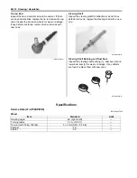
5) Remove the following parts from the handlebars
(right side).
a) Right grip (1)
b) Front brake master cylinder/Front brake lever (2)
CAUTION
!
Do not turn the front brake master cylinder
upside down.
c) Throttle lever case (3)
6) Remove the following parts from left handlebars (left
side).
a) Left grip (4)
b) Left switch box (5)
c) Horn button (For P-17, 24)
d) Emergency switch (For P-17)
7) Disconnect the parking brake cable (6) from left
brake lever.
8) Remove the clamp.
I931G3620001-01
1
2
3
I931G3620002-01
4
5
I931G3620003-01
6
I931H1620004-01
I931G3620004-01
Summary of Contents for 2009 LT-A750XK9
Page 2: ......
Page 4: ......
Page 5: ...SUPPLEMENTS L LT A750XK9 09 MODEL 10 LT A750XPK9 09 MODEL 11 ...
Page 29: ...0A 15 General Information 99565 01010 013 CD ROM Ver 13 ...
Page 57: ...0B 28 Maintenance and Lubrication 09915 40610 Oil filter wrench Page 0B 12 Page 0B 12 ...
Page 68: ...0C 11 Service Data ...
Page 310: ...1K 5 Exhaust System ...
Page 482: ...4D 6 Parking Brake ...
Page 528: ...6B 13 Steering Handlebar ...
Page 581: ......


