3D-4 Propeller Shafts:
Assembly
CAUTION
!
The removed bearing, snap rings, oil seal, C-
ring and O-rings must be replaced with new
ones.
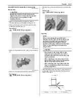
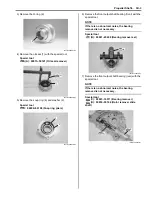
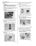
1) Install the front output shaft bearing (rear) (1) to the
right crankcase with the special tool.
Special tool
(A): 09913–70210 (Bearing installer set)
2) Install the front output shaft bearing (front) to the
front output shaft housing with the special tool.
Special tool
(A): 09913–70210 (Bearing installer set)
3) Install the washer (2) and snap ring (3).
Special tool
: 09900–06108 (Snap ring pliers)
4) Install the oil seal (4) with the suitable socket
wrench.
5) Apply grease to the oil seal lip.
: Grease 99000–25160 (Water resistance
grease)
6) Install the O-ring (5) to the front drive collar.
7) Apply grease to the O-ring (5).
: Grease 99000–25010 (SUZUKI SUPER
GREASE A or equivalent)
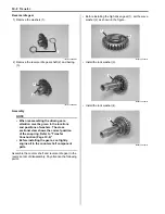
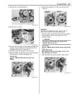
8) Install the output shaft housing (6) and front drive
collar assembly (7) to the front output shaft.
9) Install the snap ring (8), C-ring (9) and O-ring.
10) Apply a small quantity of grease to the O-ring.
: Grease 99000–25010 (SUZUKI SUPER
GREASE A or equivalent)
1
(A)
I831G1340012-01
(A)
I831G1340013-01
2
3
I831G1340014-02
4
4
I831G1340015-04
5
I831G1340016-02
6
7
9
8
I831G1340017-02
Summary of Contents for 2009 LT-A750XK9
Page 2: ......
Page 4: ......
Page 5: ...SUPPLEMENTS L LT A750XK9 09 MODEL 10 LT A750XPK9 09 MODEL 11 ...
Page 29: ...0A 15 General Information 99565 01010 013 CD ROM Ver 13 ...
Page 57: ...0B 28 Maintenance and Lubrication 09915 40610 Oil filter wrench Page 0B 12 Page 0B 12 ...
Page 68: ...0C 11 Service Data ...
Page 310: ...1K 5 Exhaust System ...
Page 482: ...4D 6 Parking Brake ...
Page 528: ...6B 13 Steering Handlebar ...
Page 581: ......

