Engine Mechanical: 1D-24
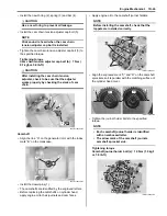
• Tighten the cylinder base nuts (5) to the specified
torque.
Tightening torque
Cylinder base nut (c): 10 N·m (1.0 kgf-m, 7.0 lb-ft)
Cam Drive Idle Gear / Sprocket
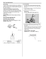
• Align the match mark “A” on the generator rotor with
the mark “B” on the crankcase.
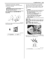
• Install the cam drive idle gear/sprocket (1) onto the
cylinder head and cam chain on it. When installing the
cam drive idle gear/sprocket, align the punched mark
“A” on the cam drive gear/sprocket (1) with the
embossed line “B” on the cylinder head.
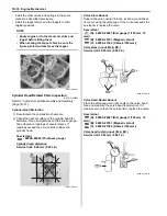
• Install the cam drive idle gear/sprocket shaft (2),
copper washer (3) and shim (4).
CAUTION
!
When checking the positions, remove the
cam chain slack at the cam chain guide side
by holding the cam drive idle gear/sprocket
by hand.
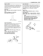
NOTE
Due to special valve train mechanism,
aligning of the three elements; the punched
mark “C”, embossed line “D” and the gear
tooth root on the cam drive idle gear/
sprocket; can occur once every other
rotation of crankshaft.
CAUTION
!
If the punched mark “C” does not align the
embossed line “D”, turn the crankshaft 360
°
(1 turn) to bring the line on the generator
rotor to the index mark on the crankcase
again and reinstall the cam drive idle gear/
sprocket to the correct position as shown in
the figure.
(c)
5
I831G1140116-02
“A”
“B”
I831G1140117-02
“A”
“B”
1
I831G1140118-01
2
3
4
I831G1140119-01
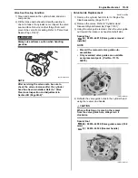
Summary of Contents for 2009 LT-A750XK9
Page 2: ......
Page 4: ......
Page 5: ...SUPPLEMENTS L LT A750XK9 09 MODEL 10 LT A750XPK9 09 MODEL 11 ...
Page 29: ...0A 15 General Information 99565 01010 013 CD ROM Ver 13 ...
Page 57: ...0B 28 Maintenance and Lubrication 09915 40610 Oil filter wrench Page 0B 12 Page 0B 12 ...
Page 68: ...0C 11 Service Data ...
Page 310: ...1K 5 Exhaust System ...
Page 482: ...4D 6 Parking Brake ...
Page 528: ...6B 13 Steering Handlebar ...
Page 581: ......


