


1A-39 Engine General Information and Diagnosis:
Step
Action
Yes
No
1
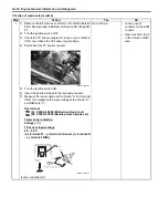
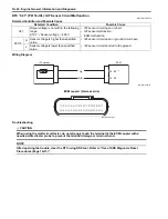
7) Disconnect the ECM coupler. Refer to “ECM Removal
and Installation in Section 1C (Page 1C-1)”.
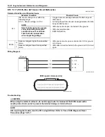
8) Check the continuity between Y wire “B” and terminal
“14”.
Also, check the continuity between R wire “A” and
terminal “6”.
Special tool
(A): 09900–25008 (Multi-circuit tester set)
(B): 09900–25009 (Needle pointed probe set)
Tester knob indication
Continuity test (
)
ECM coupler (Harness side)
Is the continuity OK?
Go to Step 2.
Y or R wire open, or Y
wire shorted to ground.
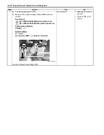
2
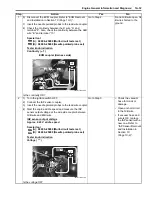
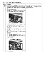
1) Correct the ECM coupler.
2) Turn the ignition switch ON.
3) Measure the input voltage between the R wire and
ground.
If OK, the measure the input voltage between the R wire
and B/Br wire.
Special tool
(A): 09900–25008 (Multi-circuit tester set)
Tester knob indication
Voltage (
)
TP sensor input voltage
4.5 – 5.5 V
((+) terminal: R – (–) terminal: Ground, (+) terminal: R
– (–) terminal: B/Br)
In the voltage OK?
Go to Step 3.
R and P/B wire open, or
P/B wire shorted to the
ground.
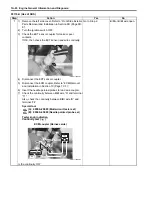
“14”
(A)
(B)
“A”
“B”
“6”
I831G1110038-03
(A)
V
I831G1110039-03
Summary of Contents for 2009 LT-A750XK9
Page 2: ......
Page 4: ......
Page 5: ...SUPPLEMENTS L LT A750XK9 09 MODEL 10 LT A750XPK9 09 MODEL 11 ...
Page 29: ...0A 15 General Information 99565 01010 013 CD ROM Ver 13 ...
Page 57: ...0B 28 Maintenance and Lubrication 09915 40610 Oil filter wrench Page 0B 12 Page 0B 12 ...
Page 68: ...0C 11 Service Data ...
Page 310: ...1K 5 Exhaust System ...
Page 482: ...4D 6 Parking Brake ...
Page 528: ...6B 13 Steering Handlebar ...
Page 581: ......