1J-6 Charging System:
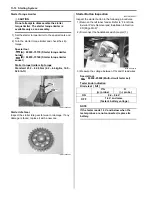
17) Remove the generator rotor assembly (10) with the
special tool.
NOTE
Remove the starter clutch if necessary. Refer
to “Starter Torque Limiter / Starter Clutch
Removal and Installation in Section 1I
(Page 1I-10)”.
Special tool
(B): 09930–30721 (Rotor remover)
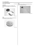
18) Remove the key (11).
19) Remove the generator stator (12) along with the
CKP sensor (13).
Installation
Install the generator in the reverse order of removal. Pay
attention to the following points:
• Tighten the generator stator set bolts and CKP sensor
mounting bolts to the specified torque.
NOTE
Be sure the grommet (1) is set to the
generator cover.
Tightening torque
Generator stator set bolt (a): 11 N·m (1.1 kgf-m,
8.0 lb-ft)
CKP sensor mounting bolt (b): 6 N·m (0.6 kgf-m,
4.5 lb-ft)
Lead wire clamp bolt (c): 6 N·m (0.6 kgf-m, 4.5 lb-
ft)
• Degrease the tapered portion “A” of generator rotor
assembly and also the crankshaft “B”. Use
nonflammable cleaning solvent to wipe off oily or
greasy matter to make these surfaces completely dry.
• Fit the key (2) in the key slot on the crankshaft.
• Install the generator rotor assembly onto crankshaft.
10
(B)
I831G11A0012-01
11
I831G11A0013-02
12
13
I831G11A0014-02
(a)
(b)
(c)
1
I831G11A0016-03
2
“B”
“A”
I831G11A0017-04
Summary of Contents for 2009 LT-A750XK9
Page 2: ......
Page 4: ......
Page 5: ...SUPPLEMENTS L LT A750XK9 09 MODEL 10 LT A750XPK9 09 MODEL 11 ...
Page 29: ...0A 15 General Information 99565 01010 013 CD ROM Ver 13 ...
Page 57: ...0B 28 Maintenance and Lubrication 09915 40610 Oil filter wrench Page 0B 12 Page 0B 12 ...
Page 68: ...0C 11 Service Data ...
Page 310: ...1K 5 Exhaust System ...
Page 482: ...4D 6 Parking Brake ...
Page 528: ...6B 13 Steering Handlebar ...
Page 581: ......


