


6B-4 Steering / Handlebar:
9) Remove the handlebar upper clamps (7) and
handlebars (8).
10) Remove the left brake lever from the handlebars (left
side).
Installation
Install the handlebars in the reverse order of removal.
Pay attention to the following points:
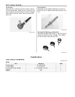
• Install the left brake lever (1) to the handlebars.
• Align the punch mark “A” on the handlebars with the
mating surface “B” of rear brake lever (1).
• Tighten the rear brake lever holder clamp bolt (2) to
the specified torque.
Tightening torque
Rear brake lever holder clamp bolt (a): 11 N·m (
1.1 kgf-m, 8.0 lbf-ft)
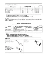
• Install the washers (3) and bolts (4) as shown in the
steering/handlebars construction. Refer to “Steering /
Handlebars Assembly Construction (LT-A750XP/ZK9)
(Page 6B-2)”.
• Set the handlebars so that its punch mark “B” aligns
with the mating surface of the left handlebar holder.
• Tighten the handlebar clamp bolts (4) to the specified
torque.
NOTE
First tighten the handlebar clamp bolts (4)
(front ones) to the specified torque.
Tightening torque
Handlebar clamp bolt (b): 26 N·m (2.6 kgf-m, 19.0
lbf-ft)
8
7
I931G3620027-01
I831G1620006-05
(a)
2
1
“A”
“B”
I931H1620008-01
“a”: Clearance
4
4
3
3
“B”
I931H1620009-02
“ a ”
(b)
4
(b)
FWD
I931H1620010-01
Summary of Contents for 2009 LT-A750XK9
Page 2: ......
Page 4: ......
Page 5: ...SUPPLEMENTS L LT A750XK9 09 MODEL 10 LT A750XPK9 09 MODEL 11 ...
Page 29: ...0A 15 General Information 99565 01010 013 CD ROM Ver 13 ...
Page 57: ...0B 28 Maintenance and Lubrication 09915 40610 Oil filter wrench Page 0B 12 Page 0B 12 ...
Page 68: ...0C 11 Service Data ...
Page 310: ...1K 5 Exhaust System ...
Page 482: ...4D 6 Parking Brake ...
Page 528: ...6B 13 Steering Handlebar ...
Page 581: ......