Engine Mechanical: 1D-52
Oil Strainer
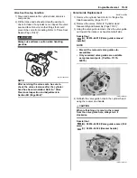
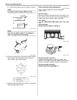
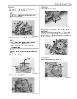
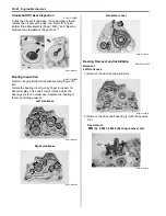
• Install the oil strainer (1).
NOTE
Fit the convex part “A” of the oil strainer in
the concave part “B” of the crankcase.
Transfer / Rear Output Shaft / Rear Output Shaft
Bevel Gear
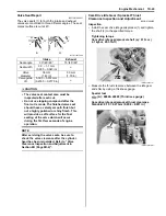
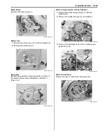
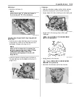
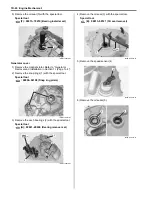
• Install the rear output shaft bevel gear (1) and rear
output shaft (2). Refer to “Transfer Removal and
Installation in Section 3C (Page 3C-3)”.
NOTE
Measure the backlash before installing the
transfer component parts (3). Refer to “Rear
Output Shaft Drive Bevel Gear Shim
Inspection and Adjustment in Section 3D
(Page 3D-11)”.
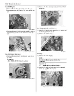
• Install the transfer component parts (3). Refer to
“Transfer Removal and Installation in Section 3C
(Page 3C-3)”.
Crankcase
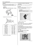
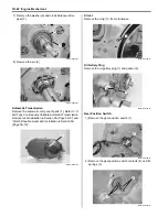
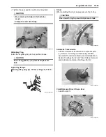
• Wipe the crankcase mating surface (both surfaces).
• Insert the dowel pins (1) onto the left crankcase.
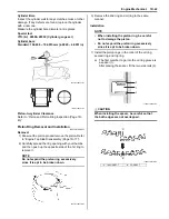
• Apply engine oil to the conrod big end and each gear.
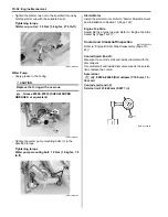
• Apply bond to the mating surface of the right
crankcase.
: Sealant 99000–31110 (SUZUKI BOND
No.1215 or equivalent)
• Apply grease to the oil seals.
: Grease 99000–25010 (SUZUKI SUPER
GREASE A or equivalent)
• Assemble the crankcase with in few minutes.
“A”
“B”
1
I831G1140246-01
2
3
1
I831G1140247-02
1
I831G1140248-03
I831G1140252-01
I831G1140250-01
Summary of Contents for 2009 LT-A750XK9
Page 2: ......
Page 4: ......
Page 5: ...SUPPLEMENTS L LT A750XK9 09 MODEL 10 LT A750XPK9 09 MODEL 11 ...
Page 29: ...0A 15 General Information 99565 01010 013 CD ROM Ver 13 ...
Page 57: ...0B 28 Maintenance and Lubrication 09915 40610 Oil filter wrench Page 0B 12 Page 0B 12 ...
Page 68: ...0C 11 Service Data ...
Page 310: ...1K 5 Exhaust System ...
Page 482: ...4D 6 Parking Brake ...
Page 528: ...6B 13 Steering Handlebar ...
Page 581: ......

