


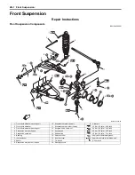

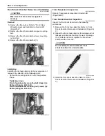


Front Suspension: 2B-6
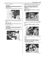
• Install the cotter pins (4).
CAUTION
!
The removed cotter pins (4) must be replaced
with new ones.
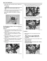
• Connect the tie-rod end (5) to the steering knuckle (6)
and tighten the tie-rod end nut (7) to the specified
torque.
Tightening torque
Tie-rod end nut (b): 29 N·m (2.9 kgf-m, 21.0 lb-ft)
• Install the cotter pin (8).
CAUTION
!
The removed cotter pin (8) must be replaced
with a new one.
• Apply thread lock to the brake disc cover mounting
bolts (9) and tighten them to the specified torque.
: Thread lock cement 99000–32130
(THREAD LOCK CEMENT SUPER 1360 or
equivalent)
Tightening torque
Brake disc cover mounting bolt (c): 10 N·m (1.0
kgf-m, 7.0 lb-ft)
• Apply grease to the wheel hub spline and lip of dust
seal.
: Grease 99000–25160 (Water resistance
grease)
• Install the wheel hub (10), washer (11) and front hub
nut (12).
NOTE
The conical side of washer (11) faces out
side. Refer to “Front Suspension Assembly
Construction (Page 2B-2)”.
4
4
I831G1220018-01
6
8
5
(b)
7
I831G1220019-01
(c)
9
I831G1220020-01
I831G1220021-01
12
10
11
I831G1220022-01
Summary of Contents for 2009 LT-A750XK9
Page 2: ......
Page 4: ......
Page 5: ...SUPPLEMENTS L LT A750XK9 09 MODEL 10 LT A750XPK9 09 MODEL 11 ...
Page 29: ...0A 15 General Information 99565 01010 013 CD ROM Ver 13 ...
Page 57: ...0B 28 Maintenance and Lubrication 09915 40610 Oil filter wrench Page 0B 12 Page 0B 12 ...
Page 68: ...0C 11 Service Data ...
Page 310: ...1K 5 Exhaust System ...
Page 482: ...4D 6 Parking Brake ...
Page 528: ...6B 13 Steering Handlebar ...
Page 581: ......


