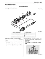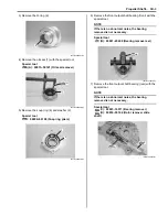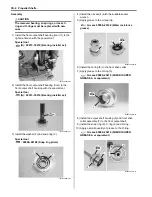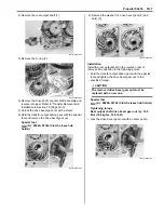
3C-14 Transfer:
Installation
Install the gear position switch in the reverse order of
removal. Pay attention to the following points:
• Apply grease to the O-ring.
CAUTION
!
Replace the O-ring with a new one.
: Grease 99000–25010 (SUZUKI SUPER
GREASE A or equivalent)
• Tighten the gear position switch bolts (1).
• Route the gear position switch lead wire. Refer to
“Wiring Harness Routing Diagram in Section 9A
(Page 9A-4)”.
• Install the V-belt inner cover. Refer to “Clutch Shoe
Removal and Installation in Section 5A (Page 5A-16)”.
• Install the drive V-belt. Refer to “V-belt Type
Continuously Variable Automatic Transmission
Removal and Installation in Section 5A (Page 5A-5)”.
• Install the removed parts.
Gearshift Shaft No. 2 / Gearshift Cam Plate
Removal and Installation
B831G23306014
Removal
Refer to “Shift Lever Assembly Removal and Installation
in Section 5A (Page 5A-24)”.
1) Drain engine oil. Refer to “Engine Oil and Filter
Replacement in Section 0B (Page 0B-10)”.
2) Drain engine coolant. Refer to “Cooling System
Inspection in Section 0B (Page 0B-15)”.
3) Remove the gearshift arm (1).
4) Remove the generator cover. Refer to “Generator
Removal and Installation in Section 1J (Page 1J-4)”.
5) Remove the gearshift shaft assembly (2) and
washers (3).
I831G1330046-01
1
I831G1330047-03
1
I831G1330048-01
3
2
I831G1330049-02
Summary of Contents for 2009 LT-A750XK9
Page 2: ......
Page 4: ......
Page 5: ...SUPPLEMENTS L LT A750XK9 09 MODEL 10 LT A750XPK9 09 MODEL 11 ...
Page 29: ...0A 15 General Information 99565 01010 013 CD ROM Ver 13 ...
Page 57: ...0B 28 Maintenance and Lubrication 09915 40610 Oil filter wrench Page 0B 12 Page 0B 12 ...
Page 68: ...0C 11 Service Data ...
Page 310: ...1K 5 Exhaust System ...
Page 482: ...4D 6 Parking Brake ...
Page 528: ...6B 13 Steering Handlebar ...
Page 581: ......


